Compensating pressure regulator

a pressure regulator and compensating technology, applied in the field of pneumatic tools, can solve the problems of limited range, limited number of operating devices, and safety of tripping over cords and hoses, and achieve the effect of simple design and easy manufacturing

Inactive Publication Date: 2013-11-19
CARVER JARED
View PDF11 Cites 0 Cited by
  • Summary
  • Abstract
  • Description
  • Claims
  • Application Information

AI Technical Summary

Benefits of technology

[0021]Yet a further embodiment of the present invention is to provide a compen

Problems solved by technology

The disadvantages are clearly evident such as safety from tripping over cords and hoses, limited range, limited number of operating devices, and the need to transport heavy generators and compressors to construction sites.
In regards to portable powered devices using compre

Method used


Image

  • Compensating pressure regulator
  • Compensating pressure regulator
  • Compensating pressure regulator

Examples


Embodiment Construction

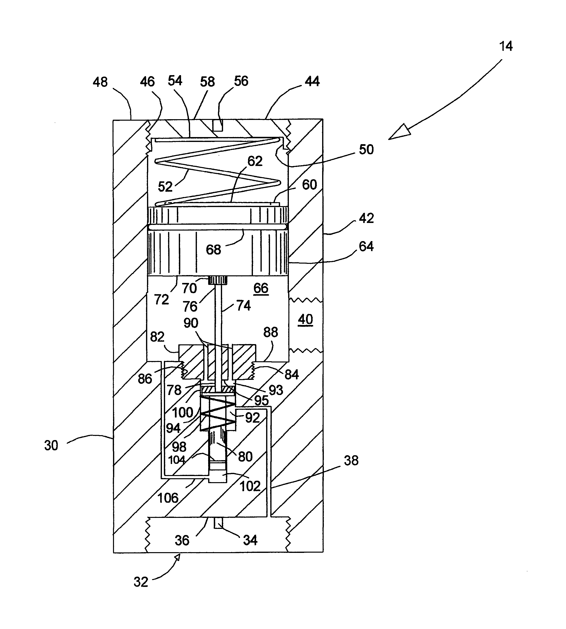
[0028]The present invention is directed at a pressure regulator for use on portable tools using a portable source of compressed gas.

[0029]It should be understood that the present invention is not limited to use on portable compressed gas cylinders, but may be used on any source of pressurized gas or fluids to reduce or substantially eliminate pressure transient conditions such as spikes, either high pressure or low pressure, and is not limited to the use on construction tools, but other devices that require substantially uniform operating pressures. Any and all cited references are incorporated by reference hereto as to their teachings.

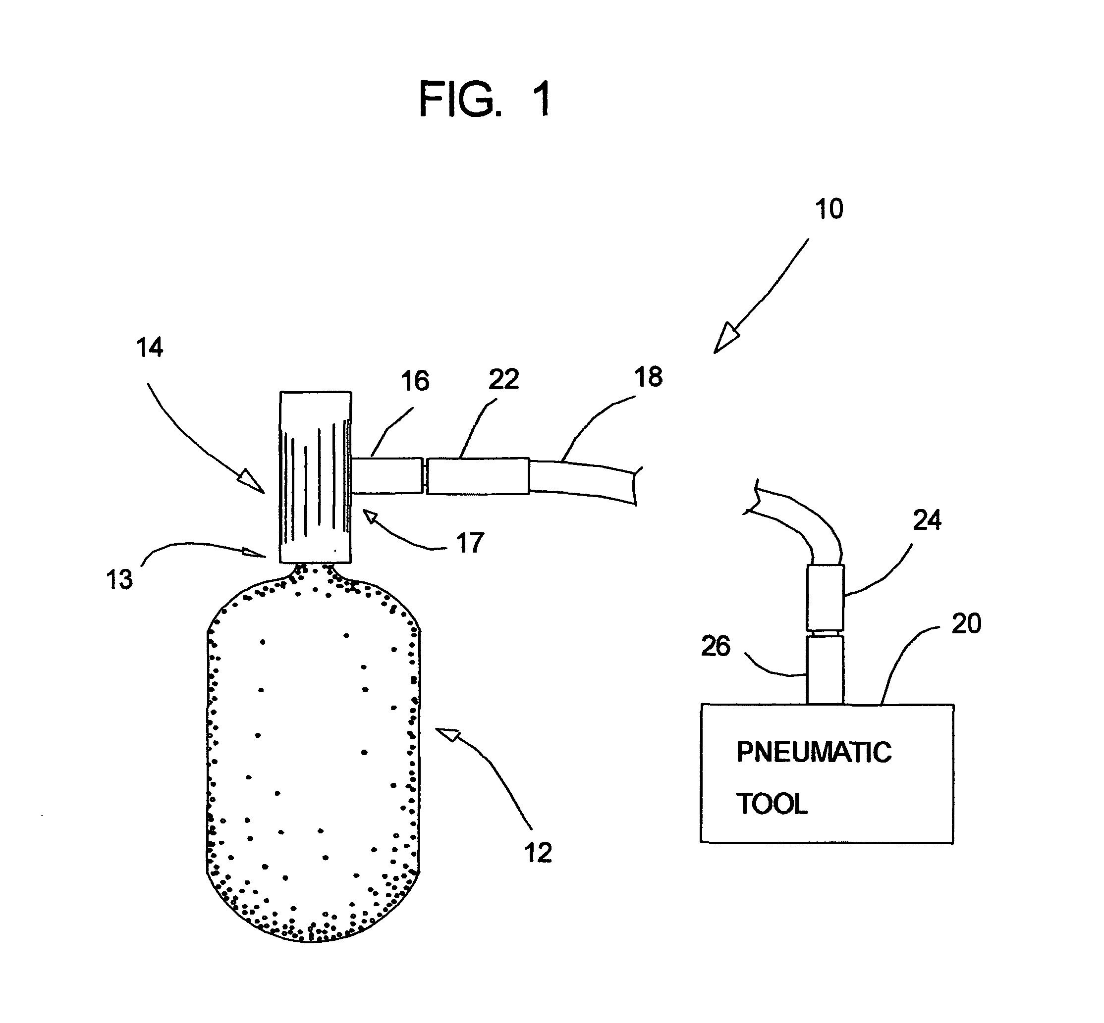
[0030]Turning to the drawings, wherein like components are designated by like reference numerals throughout the various figures, attention is initially directed to FIG. 1 which illustrates by schematic view a portal compressed gas operated tool system 10 constructed according to the present invention.

[0031]As best shown in FIG. 1, a portable bottle 12...


PUM


Abstract

A compensating pressure regulator comprising a single stage regulating device for controlling the flow of compressed gas therethrough; and a compensating device for automatically adjusting transient pressure conditions to provide a substantially uniform gas pressure output by use of a pin like-piston having dual sources of pressure thereon. The compensating pressure regulator for use with bottled gas on portable tools.

Description

CROSS REFERENCES TO RELATED APPLICATIONS[0001]This is the regular utility application as filed from U.S. Provisional Patent Application Ser. No. 61 / 208,731 filed Feb. 27, 2009 by the same inventor, and claims priority to such.REFERENCE TO FEDERALLY SPONSORED RESEARCH OR DEVELOPMENT[0002]NAREFERENCE TO JOINT RESEARCH AGREEMENTS[0003]NAREFERENCE TO SEQUENCE LISTING[0004]NABACKGROUND OF THE INVENTION[0005]1. Field of the Invention[0006]The present invention relates generally to pneumatic tools, and, particularly, relates to portable pneumatic tools, and, in greater particularly, relates to devices for controlling the flow of gas thereto.[0007]2. Description of the Prior Art[0008]With the advancement of technology in the construction industry, the use of powered portable devices has become more common. Typically, such devices were powered by an electric generator which converted the AC to DC power as needed or ran a compressor. The powered devices were connected by long electrical cords...

Claims


Application Information

Patent Timeline
IPC IPC(8): F16K31/12
CPCF16K31/12G05D16/107Y10T137/7801Y10T137/7826
Inventor CARVER, JARED
Owner CARVER JARED
Why Eureka
Try Eureka