Pivotable seat

a seat and reclining technology, applied in the field of seats, can solve the problems of tissue or decubitus death, poor blood circulation, special cushions, etc., and achieve the effect of reducing the angle l, enhancing the flow of blood and moisture in the surrounding tissue, and reducing the risk of decubitus

Active Publication Date: 2013-11-19
PR SELLA
View PDF29 Cites 32 Cited by
  • Summary
  • Abstract
  • Description
  • Claims
  • Application Information

AI Technical Summary

Benefits of technology

[0040]By tilting the left-hand supporting surface further forward (reducing angle φL) the left tuber will be loaded more than the right tuber. By varying the left and right seat angle (respectively φL and φR) the loads on the tubera will begin to vary, this enhancing flow of blood

Problems solved by technology

Seated persons who are more or less forced to sit for long periods hereby experience problems related to this sitting.
Sitting-related problems manifest themselves in, among other ways, pain in the bottom area, this sometimes even resulting in death of tissue or decubitus.
The poor blood circulation is caused, among other reasons, by the fact that a relatively high pressure locally on and in the tissue reduces the flow through the blood vessels.
Unfortunately, existing products such as special cushions, so-called anti-decubitus cushions, still provide little or no improvement for such patients.
It is not possible in the case of such mechanisms to refer to a single pivot axis, but there is a region around which the pivoting movement takes place.
This can only be achieved with a correct choice of the seat a

Method used


Image

  • Pivotable seat
  • Pivotable seat
  • Pivotable seat

Examples


Embodiment Construction

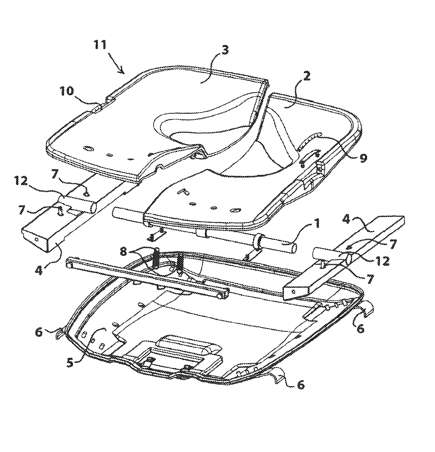
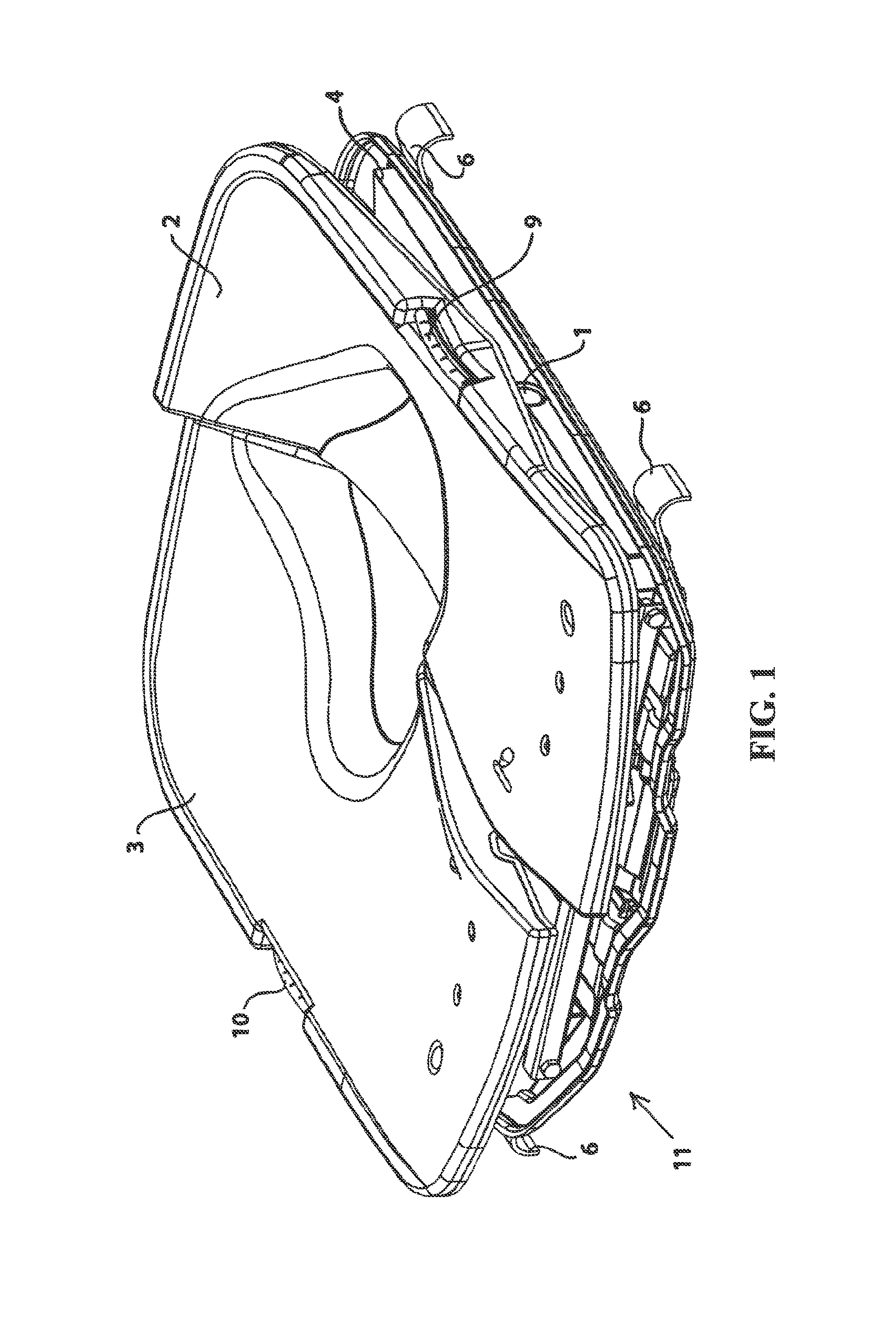
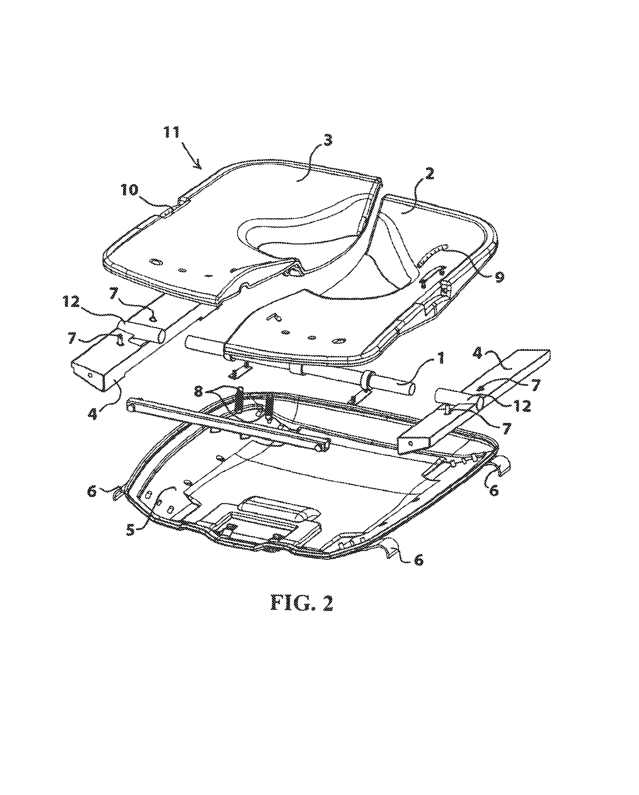
[0056]FIGS. 1 and 2 show a seat 11 according to the invention. Seat 11 comprises a profiled bottom plate or shell 5 of for instance a rigid plastic, a bearing construction 4 supported thereby, a pivot shaft 1 which is carried thereby via bushes 12 and to which a left-hand seat part 2 and a right-hand seat part 3 are pivotally connected. In the shown situation the left-hand seat part 2 is pivoted further forward / downward than right-hand seat part 3.

[0057]The upper surfaces of seat parts 2 and 3 have an anatomical form.

[0058]It is noted that the pressure-distributing layers and cover layer to be further described below are not shown in FIGS. 1 and 2 for the sake of clarity.

[0059]Bottom plate 5 carries on its four corner points outward protruding hooks 6 for coupling to for instance the frame of a chair or a wheelchair.

[0060]In this exemplary embodiment frames 4 comprise adjustable fixation means 7 for securing or bounding the pivoting range of seat parts 2 and / or 3.

[0061]The sitting c...


PUM


Abstract

A seat for supporting the bottom area of a seated person, which seat is intended and adapted to form part of an article of seating furniture, such as a chair or a couch, a seat for a means of transport such as a car, a bus or an aircraft, or a wheelchair, has the feature that the seat consists of two parts, i.e. a left-hand seat part and a right-hand seat part, which seat parts are separated from each other along the nominal median plane of a user, each of the seat parts is pivotable around a pivot zone extending at least roughly perpendicularly of said median plane; and the projected position of the pivot zone lies in front of the tubera.

Description

CROSS-REFERENCES TO RELATED APPLICATIONS[0001]This application is a National Stage application of International Patent Application No. PCT / NL2008 / 050861 filed Dec. 30, 2008 and published as International Publication No. WO 2009 / 084962 A1 on Jul. 9, 2009, which claims priority to Netherlands Patent Application No. NL2001147 filed Dec. 31, 2007, the entire contents of applications is incorporated herein by this reference.BACKGROUND AND SUMMARY OF INVENTION[0002]The invention relates to a seat for supporting the bottom area of a seated person, which seat is intended and adapted to form part of an article of seating furniture, such as a chair or a couch, a seat for a means of transport such as a car, a bus or an aircraft, or a wheelchair.[0003]Such a seat is known in many embodiments and is usually applied in combination with a backrest.[0004]The invention has for its object to embody a known seat such that the shear forces on the upper legs and buttocks are reduced and the pressure on ...

Claims


Application Information

Patent Timeline
IPC IPC(8): B60N2/02A47C7/62A47C1/022A47C7/50
CPCA47C7/024A47C7/14A47C7/503A61G7/0573A47C7/744A47C7/144
Inventor HUTTENHUIS, ALOUISIUS GERARDUS
Owner PR SELLA
Why Eureka
Try Eureka