
Audio driver

a driver and audio technology, applied in the direction of deaf-aid sets, electrical transducers, transducer details, etc., can solve the problems of inefficient sound production, achieve the effect of improving air flow, improving sound quality, and improving simultaneous sound production

Inactive Publication Date: 2013-11-19
KONINK PHILIPS ELECTRONICS NV
View PDF18 Cites 3 Cited by
  • Summary
  • Abstract
  • Description
  • Claims
  • Application Information

AI Technical Summary

Benefits of technology

The design achieves improved sound quality and air flow generation while reducing complexity and cost, enabling dual functionalities like sound radiation and air flow generation without significant impact on either performance.

Problems solved by technology

Specifically, conventional acoustic cooling is optimized for efficient generation of air flows while maintaining quiet operation and they therefore tend to be very inefficient for producing sound.

Method used


Image

  • Audio driver
  • Audio driver
  • Audio driver

Examples


Embodiment Construction

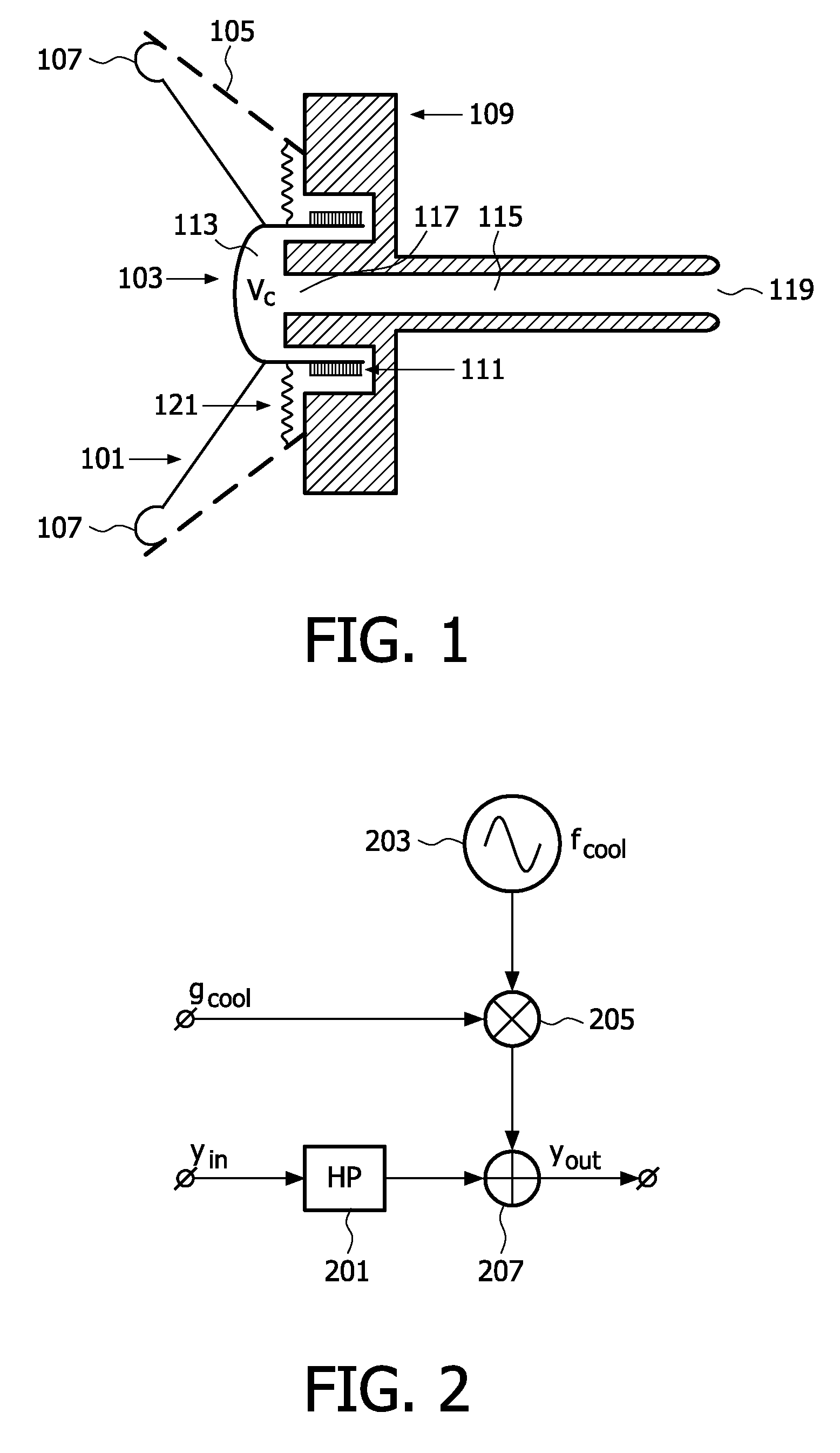
[0054]FIG. 1 illustrates an example of cross sectional view of an audio driver in accordance with some embodiments of the invention. The audio driver is specifically a loudspeaker unit.

[0055]The audio driver of FIG. 1 provides dual functionalities and can be used to simultaneously generate an audio / sound output and an air flow output which for example may be used for cooling. Thus the audio driver allows different functionalities to be implemented by a single driver and can for example be implemented in an electronic device, such as a computer, to provide simultaneous sound generation and acoustic cooling.

[0056]The audio driver comprises a diaphragm which in the specific example is made up by a membrane 101 and a central dust cap 103. The membrane 101 is attached to a speaker frame 105 by an elastic suspension 107 allowing the diaphragm to move relative to the speaker frame. The speaker frame is fixedly connected to a transducer element 109, 111 which comprises a fixed part 109 (whi...


PUM


Abstract

An audio driver including a diaphragm with a first side and a second side. The diaphragm is coupled to a transducer element on the second side and is arranged to radiate sound. The transducer element converts an electrical input signal into movement of the diaphragm. The diaphragm is arranged such that a part of the diaphragm at least partly forms a cavity at the second side of an air conduit is coupled to the cavity. The air conduit has a first opening into the cavity and a second opening outside of the cavity. The air conduit and cavity form a resonator which has a resonance frequency that is less than half a free air acoustic resonance frequency of the audio driver.

Description

FIELD OF THE INVENTION[0001]The invention relates to an audio driver and in particular to an audio driver capable of simultaneously radiating sound and generating an air flow.BACKGROUND OF THE INVENTION[0002]In many applications, active cooling of e.g. electronics circuitry is desirable or necessary. Typically such cooling is implemented as air cooling using mechanical fans or in more extreme cases water or other liquid cooling.[0003]However, it has been proposed to also use air cooling based on acoustic coolers that generate an air flow. Indeed, it has been shown that in many applications such acoustic cooling is advantageous as a replacement for fans for reasons of efficiency and lifetime expectancy. For these applications, the acoustic cooler is optimized to cool as much as possible while still being quiet. An acoustic cooling is typically implemented as an acoustic transducer, such as a loudspeaker, which is optimized to generate an air flow rather than to produce sound. An exam...

Claims


Application Information

Patent Timeline
Patent Type & Authority Patents(United States)
IPC IPC(8): H04R25/00
CPCH04R9/022
Inventor OUWELTJES, OKKENIEUWENDIJK, JORIS ADELBERT MARIAKOOIJMAN, GERBENAARTS, RONALDUS MARIA
Owner KONINK PHILIPS ELECTRONICS NV
Learn More