Inverter mounting structure for vehicle

a technology for mounting structures and inverters, which is applied in the direction of electric propulsion mounting, vehicle sub-unit features, electric apparatus casings/cabinets/drawers, etc., can solve the problems of reducing the interior space of the vehicle, and it is difficult to separate the inverter and the master cylinder, so as to prevent the deformation of the inverter bracket, and suppress the master cylinder or the dash panel

Active Publication Date: 2013-12-03
SUZUKI MOTOR CORP
View PDF26 Cites 11 Cited by
  • Summary
  • Abstract
  • Description
  • Claims
  • Application Information

AI Technical Summary

Benefits of technology

[0010]Therefore, according to an embodiment of the present invention, the inverter bracket is made of casting. Hence, when a force is exerted from the front side of the vehicle onto the supporting portion of the inverter bracket, it is possible to prevent the deformation of the inverter bracket itself and the side member to which the inverter bracket is attached. As a result, apart of the side member between the part to which the suspension tower is coupled and another part to which the inverter bracket is attached can be made weaker than these parts. In this situation, the vehicle rear end portion of the attachment portion is provided such that the inverter bracket is located on the front side in the vehicle by a prescribed distance from the vehicle front surface portion of the suspension tower. When the force is exerted from the front side of the vehicle, a part of the side member between the part to which the suspension tower is coupled and another part to which the inverter bracket is attached is inflected outward in the vehicle width direction. Accordingly, the inverter bracket and the inverter are pushed obliquely outward in the vehicle width direction. This suppresses the master cylinder from being pushed rearward in the vehicle. As a result, it is possible to suppress the master cylinder or the dash panel from being pushed into the vehicle interior.
[0011]In addition, the protector having the inclined surface inclined at least rearward to the outside in the vehicle width direction from the inside in the vehicle width direction is attached onto the wall surface of the master cylinder facing the inverter. Even if the force exerted from the front side of the vehicle brings the inverter into contact with the master cylinder, the inverter is pushed obliquely outward in the vehicle width direction along the inclined surface of the protector. Consequently, it is possible to suppress the master cylinder or the dash panel from being pushed into the vehicle interior. As a result, it is possible to suppress the master cylinder or the dash panel from being pushed into the vehicle interior.
[0012]Furthermore, in a case where the connector for connecting electric wires is provided on the wall surface of the inverter facing the master cylinder, the protector covering the connector is capable of protecting the connector of the inverter, even if the force is exerted from the front side of the vehicle.

Problems solved by technology

This might reduce the space in the vehicle interior.
However, there is a limitation in the length in the front-rear direction of the engine room, and therefore it is difficult to separate the inverter and the master cylinder so that they will not come into contact with each other when the load is applied from the front side of the vehicle.

Method used


Image

  • Inverter mounting structure for vehicle
  • Inverter mounting structure for vehicle
  • Inverter mounting structure for vehicle

Examples


Embodiment Construction

[0021]Embodiments of the present invention will now be described with reference to the drawings.

[0022]Now, an embodiment of an inverter mounting structure of a vehicle according to the present invention will be described with reference to the drawings.

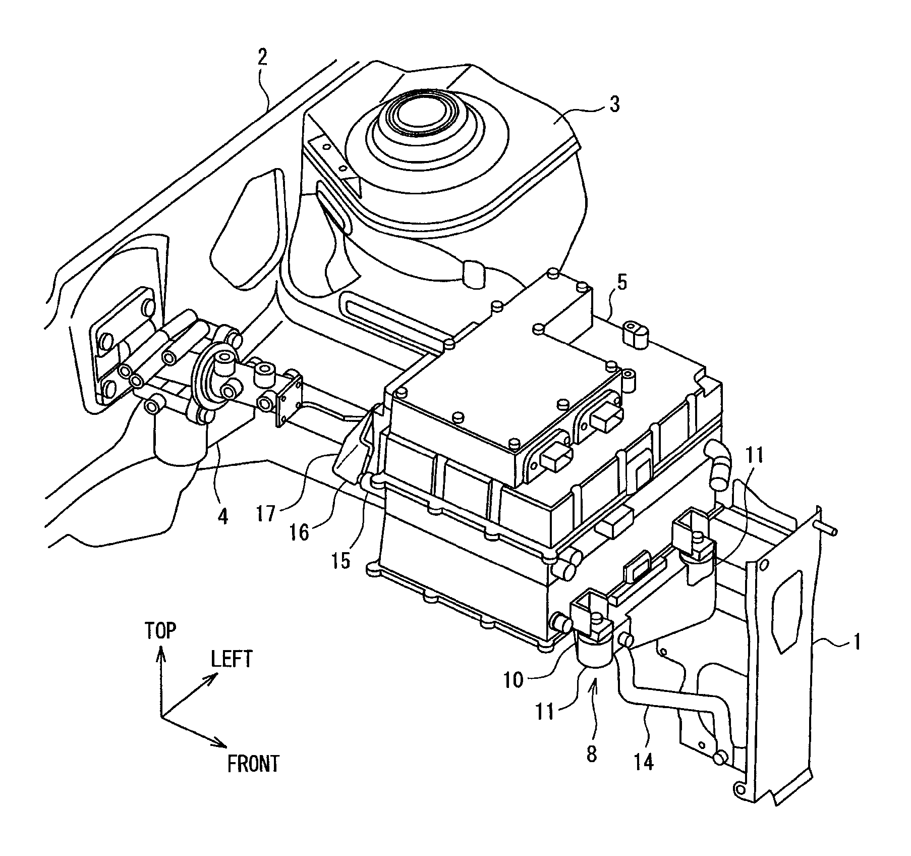
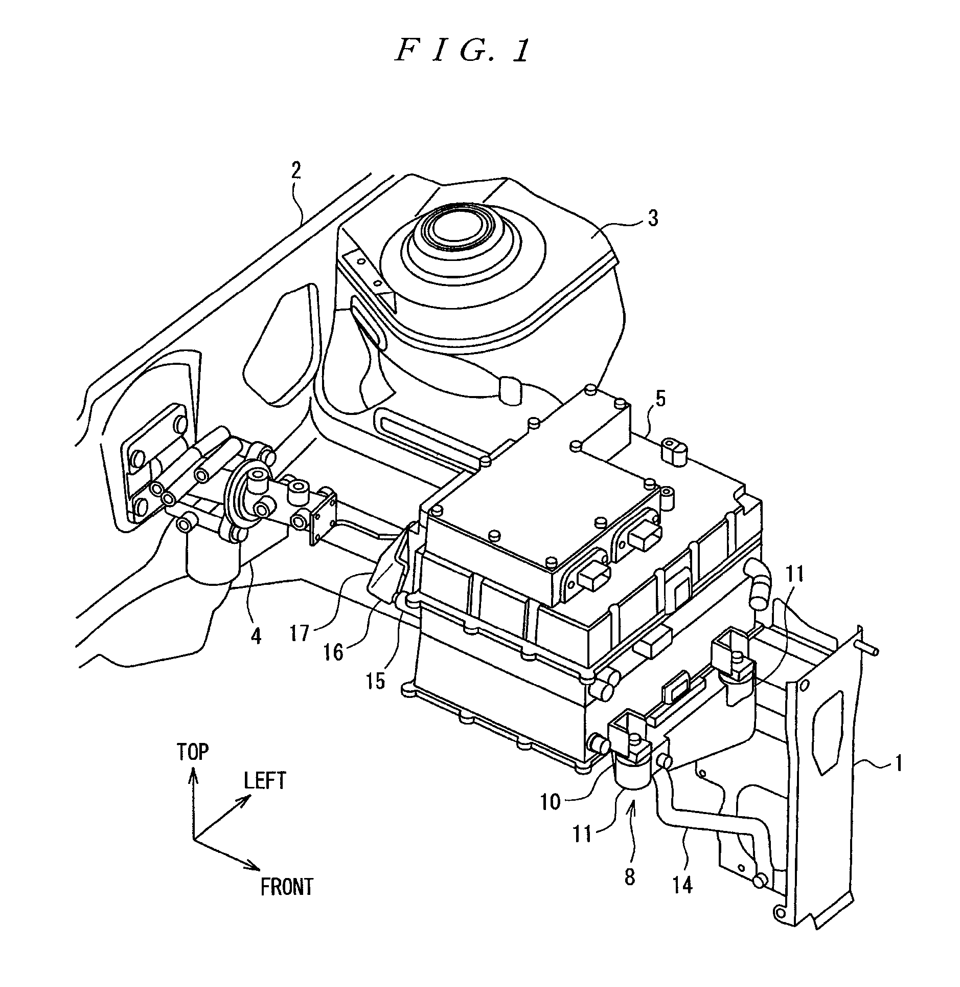
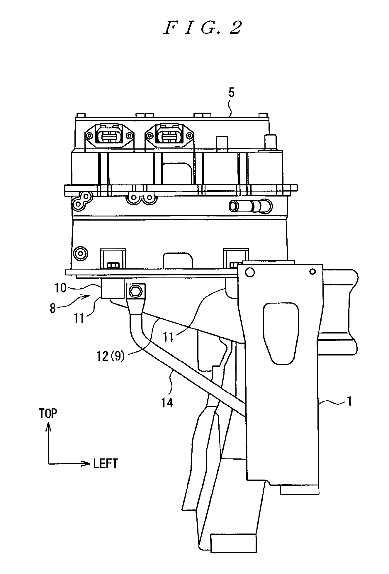
[0023]FIG. 1 is a perspective view of a front left part of an engine room illustrative of an inverter mounting structure of a vehicle according to the present embodiment. FIG. 2 is a front view of the engine room of FIG. 1. FIG. 3 is a plan view of the engine room of FIG. 1. FIG. 4 is an inner side surface view of the engine room of FIG. 1. FIG. 5 is a perspective view of a side member and an inverter bracket of FIG. 1, when they are viewed from obliquely right rear side. FIG. 6 is a plan view of the side member and the inverter bracket of FIG. 5. Specifically, the vehicle according to the present embodiment is a hybrid vehicle to be driven by an engine and a motor.

[0024]Reference numeral 1 in the drawings is a side member being longit...


PUM


Abstract

A supporting portion of an inverter bracket is made of cast, and the inverter bracket is attached onto the side member to locate a vehicle rear end portion of the attachment portion to be on the front side in the vehicle, by a prescribed distance from a vehicle front surface portion of the suspension tower. When a force F is exerted from the front side of the vehicle, the side member curves outward in the vehicle width direction between one part to which the suspension tower is coupled and another part to which the inverter bracket is attached. The inverter bracket and inverter are pushed obliquely outward in the vehicle width direction, so that the contact with the master cylinder can be suppressed.

Description

CROSS-REFERENCE[0001]This document claims priority to Japanese Application Number 2011-173852, filed Aug. 9, 2011, the entire content of which is hereby incorporated by reference.TECHNICAL FIELD[0002]The present invention relates to an inverter mounting structure in a vehicle to be suitable for mounting, for example, an inverter for driving a motor of an electric vehicle or a hybrid vehicle.BACKGROUND ART[0003]In order to drive the motor efficiently, it is desirable to apply alternating current to the motor. On the other hand, the output from a battery, which is an electric storage device, is direct current. Accordingly, an inverter is indispensable for a vehicle that stores electricity in a battery and that is driven by a motor, such as an electric vehicle or a hybrid vehicle. For instance, Patent Document 1 listed below describes that the inverter is mounted in an engine room on the front side of the vehicle.PRIOR ART DOCUMENTSPatent Documents[0004]Patent Document 1: JP 2009-28628...

Claims


Application Information

Patent Timeline
Patent Type & Authority Patents(United States)
IPC IPC(8): B60R16/03
CPCH05K5/0204B60K1/00H05K7/1432B60Y2306/01B60L2210/10Y02T10/72H05K7/14322
Inventor SAKAMOTO, TETSUO
Owner SUZUKI MOTOR CORP
Why Eureka
Try Eureka