Reduced-level shift overflow detection

Active Publication Date: 2013-12-03
TEXAS INSTR INC
View PDF2 Cites 0 Cited by
  • Summary
  • Abstract
  • Description
  • Claims
  • Application Information

AI Technical Summary

Benefits of technology

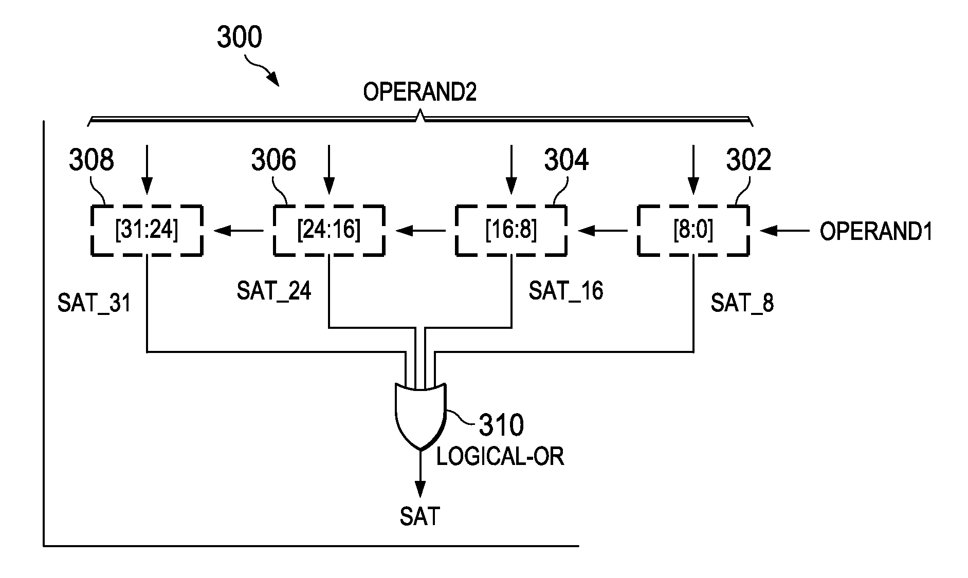
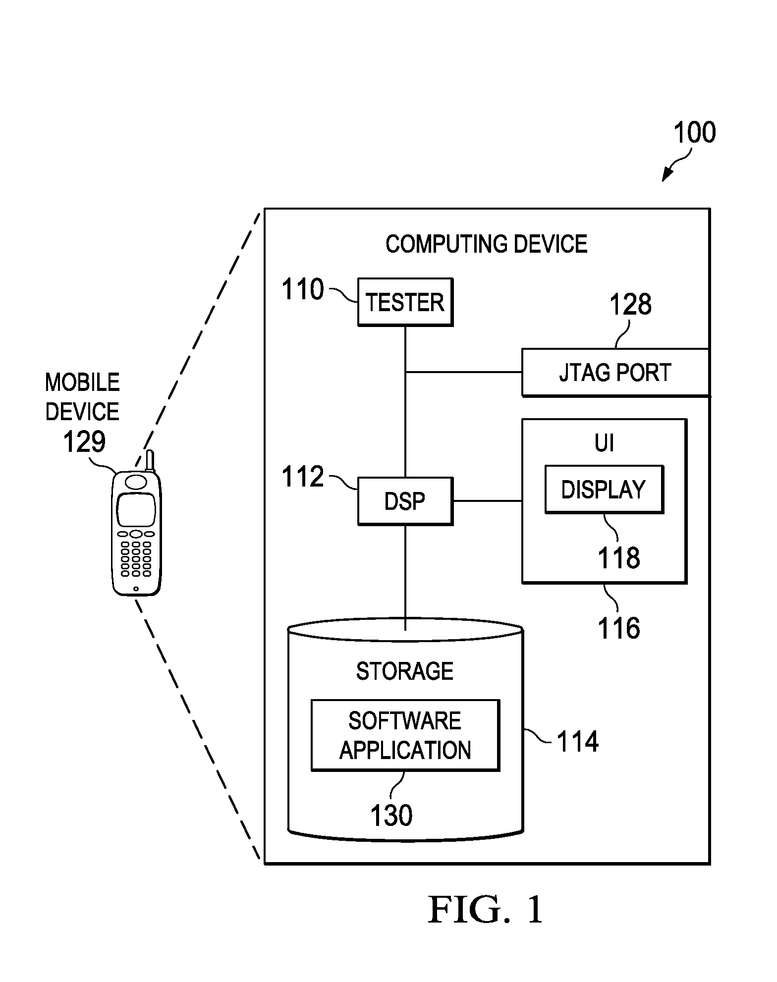
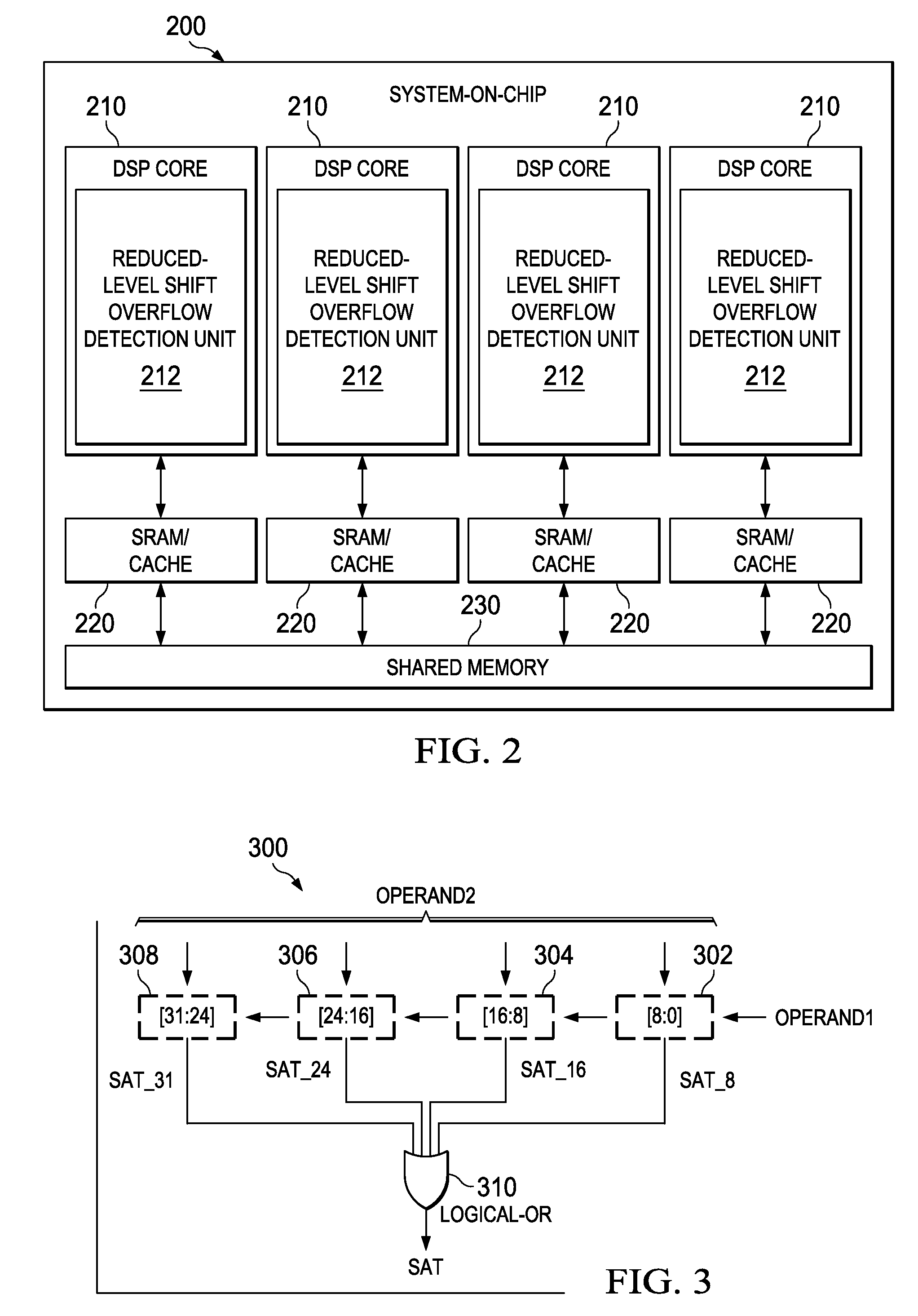
[0002]The problems noted above are solved in large part by a processor as disclosed herein that includes a shift overflow detector for rapidly detecting overflows that may result during execution of a shift instruction. Shift indication signals are generated in response to changes in logic state between adjacent pairs of bits of a receive

Problems solved by technology

The computation of this condition is often part of a timing critical path, especially if the i

Method used


Image

  • Reduced-level shift overflow detection
  • Reduced-level shift overflow detection
  • Reduced-level shift overflow detection

Examples


Example

[0010]The following discussion is directed to various embodiments of the invention. Although one or more of these embodiments may be preferred, the embodiments disclosed should not be interpreted, or otherwise used, as limiting the scope of the disclosure, including the claims. In addition, one skilled in the art will understand that the following description has broad application, and the discussion of any embodiment is meant only to be exemplary of that embodiment, and not intended to intimate that the scope of the disclosure, including the claims, is limited to that embodiment.

[0011]Certain terms are used throughout the following description and claims to refer to particular system components. As one skilled in the art will appreciate, various names may be used to refer to a component. Accordingly, distinctions are not necessarily made herein between components that differ in name but not function. In the following discussion and in the claims, the terms “including” and “comprisi...


PUM


Abstract

A processor includes a shift overflow detector for rapidly detecting overflows that may result during execution of a shift instruction. Shift indication signals are generated in response to changes in logic state between adjacent pairs of bits of a received shift data word. A received shift amount is decoded to produce decoded shift signals that indicate an amount of shifting for the received shift data word. An overflow condition is detected in response to the generated shift indication signals and the decoded shift signals and an indication of the detected overflow condition is provided.

Description

BACKGROUND[0001]One type of the instructions used in general-purpose DSP processors is a shift instruction. A shift instruction is typically a two-operand instruction. In the execution of this instruction, the data to be shifted is typically contained in one of the source operands while the amount by which the data needs to be shifted is contained in the other. A saturate condition occurs if there is an overflow in the result, when the shift data is left-shifted by the shift amount. For the specific example of signed 32-bit data, the result is limited to 0x7FFFFFFFh, which is thus considered to be the highest positive number that can be accurately represented as signed 32-bit data. The computation of this condition is often part of a timing critical path, especially if the instruction is to be executed in a single cycle, and thus can be limiting to the speed of a DSP.SUMMARY[0002]The problems noted above are solved in large part by a processor as disclosed herein that includes a shi...

Claims


Application Information

Patent Timeline
IPC IPC(8): G06F15/00
CPCG06F9/30032G06F9/30014
Inventor ANDERSON, TIMOTHY D.MOHARIL, SHRIRAM D.
Owner TEXAS INSTR INC
Why Eureka
Try Eureka