Radar and method for measuring transverse velocity of moving object

A technology of moving objects and lateral velocity, which is applied in the field of radar, can solve the problems that the measurement cannot meet real-time requirements, inconvenient operation, high cost, etc., and achieve the effect of improving recognition and tracking performance, improving detection, and measuring lateral velocity simply

Active Publication Date: 2014-07-02
WUHAN UNIV
View PDF5 Cites 8 Cited by
  • Summary
  • Abstract
  • Description
  • Claims
  • Application Information

AI Technical Summary

Problems solved by technology

In order to measure the lateral velocity, many indirect measures are adopted: when measuring the blood velocity of the human body, the sensor is moved along the blood flow direction, which is inconvenient to operate and the accuracy is poor; in the field of ocean current and atmospheric wind field measurement, two radars are used to observe the same area, Due to the information exchange and time and space matching between the two radars, the measurement cannot meet the real-time requirements, and the cost is high

Method used


Image

  • Radar and method for measuring transverse velocity of moving object
  • Radar and method for measuring transverse velocity of moving object
  • Radar and method for measuring transverse velocity of moving object

Examples


Embodiment Construction

[0024] The present invention will be further described below in conjunction with the accompanying drawings.

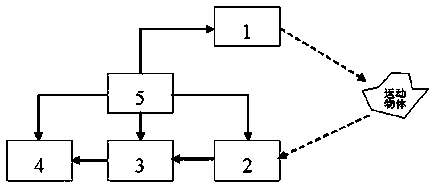
[0025] see image 3 , the lateral velocity measurement radar of moving objects based on electromagnetic wave interference in the present invention mainly includes: chirp wave transmitting unit 1, radio frequency front-end receiving unit 2, signal processing unit 3, speed display unit 4, control unit 5; The chirp wave transmitting unit, the chirp wave radio frequency front-end receiving unit, the signal processing unit and the speed display unit are connected; the chirp wave radio frequency front-end receiving unit, the signal processing unit and the speed display unit are connected in sequence.

[0026] Figure 4 Among them, the linear frequency modulation pulse wave transmitting unit includes a frequency modulation pulse wave generation circuit, a radio frequency signal generation circuit, an up-conversion circuit, a power amplifier circuit and a radiation antenna; t...


PUM


Abstract

The invention relates to a radar and method for measuring the transverse velocity of a moving object. The radar for measuring the transverse velocity of the moving object comprises a linear frequency-modulation pulse wave transmitting unit, a linear frequency-modulation pulse wave radio frequency front-end receiving unit, a signal processing unit, a control unit and a velocity display unit, wherein the control unit is connected with the linear frequency-modulation pulse wave transmitting unit, the linear frequency-modulation pulse wave radio frequency front-end receiving unit, the signal processing unit and the velocity display unit, and the linear frequency-modulation pulse wave radio frequency front-end receiving unit, the signal processing unit and the velocity display unit are connected in sequence. The radar for measuring the transverse velocity of the moving object is placed at a position a certain distance away from the moving object, two receiving circuits which are spaced from each other by a certain distance receive electromagnetic wave signals which are reflected back by the moving object, and the transverse velocity of the moving object is displayed through the display unit after processing such as mutual interference of the two paths of signals and velocity measurement is conducted. According to the radar and method for measuring the transverse velocity of the moving object, the moving object velocity detection performance, the moving object recognition performance and the moving object tracking performance of a radar system can be improved with respect to accuracy and real-time performance.

Description

technical field [0001] The invention belongs to the technical field of radar, and in particular relates to a radar and a method for measuring the lateral velocity of a moving object. Background technique [0002] Existing radars can only measure the radial velocity of moving objects using the Doppler benefit, and the lateral velocity plays a very important role in target detection, recognition and tracking. In order to measure the lateral velocity, many indirect measures are adopted: moving the sensor along the blood flow direction when measuring the blood velocity of the human body, which is inconvenient to operate and has poor accuracy; in the field of ocean current and atmospheric wind field measurement, two radars are used to observe the same area, Due to the information exchange and time and space matching between the two radars, the measurement cannot meet the real-time requirements and the cost is high. SUMMARY OF THE INVENTION [0003] In view of the above problem...

Claims


Application Information

Patent Timeline
Patent Type & Authority Applications(China)
IPC IPC(8): G01S13/58
CPCG01S7/484G01S7/4861G01S13/581
Inventor 陈章友张兰吴雄斌
Owner WUHAN UNIV
Why Eureka
Try Eureka