Pneumatic tire for motorcycle with tread wings and with sidewalls each having inner layer and outer layer

a technology of pneumatic tires and sidewalls, which is applied in the direction of cycles, non-skid devices, transportation and packaging, etc., can solve the problems of not easy to obtain tires, and achieve the effects of excellent rigidity feeling and gripping feeling in driving and braking operations, and effective suppression

Inactive Publication Date: 2013-12-10
SUMITOMO RUBBER IND LTD
View PDF7 Cites 1 Cited by
  • Summary
  • Abstract
  • Description
  • Claims
  • Application Information

AI Technical Summary

Benefits of technology

[0016]In the pneumatic tire for a motorcycle according to the present invention, the sidewall includes the inner layer having the high hardness and the outer layer having the low hardness. There is properly regulated the ratio of the thickness of the inner layer to the thickness of the outer layer on the intermediate point within the range from the inner end of the wing to the inner end of the outer layer. The tire is properly flexed in a running state. Referring to the tire, a formation of a portion having a specific distortion is effectively suppressed in the running state. The tire is excellent in a rigidity feeling and a grip feeling in driving and braking operations. In the tire, an excellent ride comfort can be maintained.

Problems solved by technology

For this reason, it is not easy to obtain the tire 2 in which a rigidity feeling and a grip feeling in driving and braking operations are enhanced without damaging a stability against a disturbance and a ride comfort.

Method used


Image

  • Pneumatic tire for motorcycle with tread wings and with sidewalls each having inner layer and outer layer
  • Pneumatic tire for motorcycle with tread wings and with sidewalls each having inner layer and outer layer
  • Pneumatic tire for motorcycle with tread wings and with sidewalls each having inner layer and outer layer

Examples


example 1

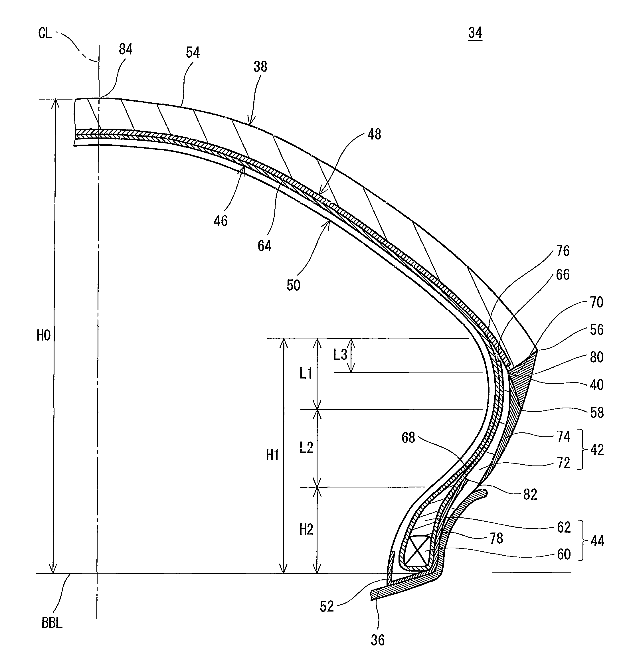
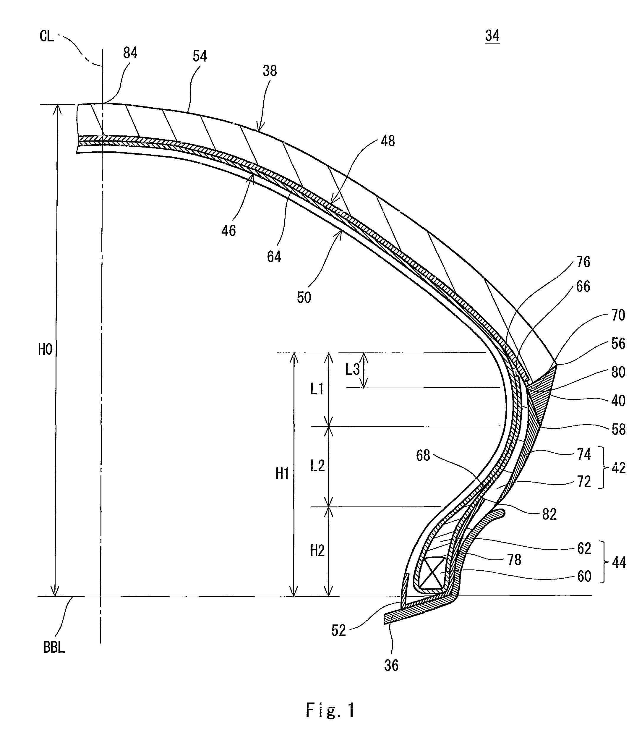
[0068]There was obtained a pneumatic tire for a motorcycle according to an example 1 which has the basic structure illustrated in FIG. 1 and a specification shown in the following Table 2. The tire has a size of “190 / 50 ZR17”. A carcass of the tire is constituted by a single carcass ply. The carcass ply is folded back from an inside toward an outside in an axial direction around a bead. A height in a radial direction from a bead base line to an end of the carcass ply which was folded back was set to be 40 mm. A height in the radial direction of an apex was set to be 10 mm. In a state in which the tire is incorporated into a rim and is filled with air, the tire has such a structure that an external surface from an inner end of a wing to an inner end of an outer layer of a sidewall takes an outward convex curved surface (taking a shape of a circular arc) in the axial direction. The structure is indicated as “A” in a column of a shape of an external surface in the Table 2.

examples 5 to 14

[0069]A tire was obtained in the same manner as in the example 1 except that a ratio (H1 / H0) of a height H1 in a radial direction from a bead base line to an outer end of an inner layer to a tire section height H0, a ratio (H2 / H0) of a height H2 in the radial direction from the bead base line to an inner end of an outer layer to the tire section height H0, a ratio (L1 / H0) of a distance L1 in the radial direction from the outer end of the inner layer to an inner end of a wing to the tire section height H0, a ratio (L2 / H0) of a distance L2 in the radial direction from the inner end of the wing to the inner end of the outer layer to the tire section height H0, and a ratio (L3 / H0) of a distance L3 in the radial direction from the outer end of the inner layer to an outer end of the outer layer to the tire section height H0 were set as shown in the following Tables 2 and 3.

examples 4 , 15 and 16

Examples 4, 15 and 16 and Comparative Examples 3 and 4

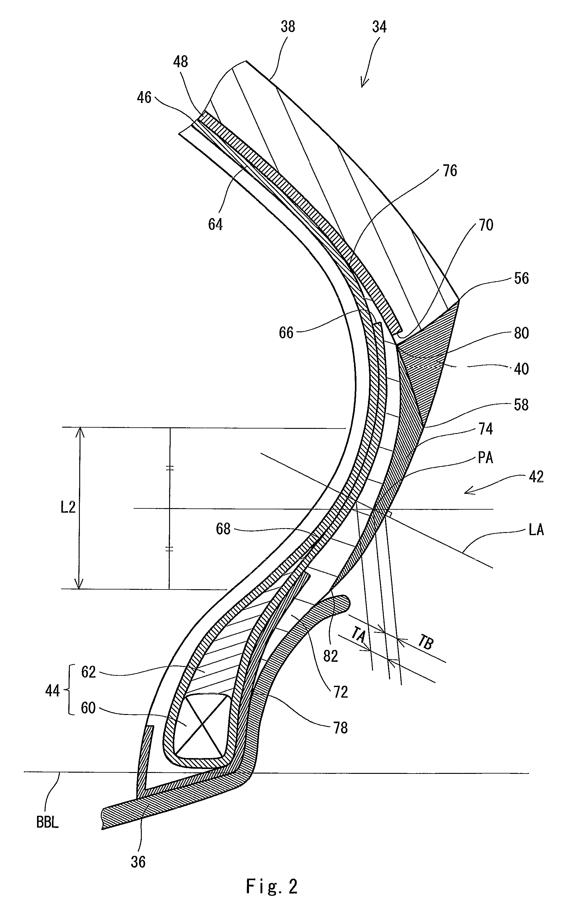
[0070]A tire was obtained in the same manner as in the example 1 except that a thickness TA of an inner layer and a thickness TB of an outer layer in a center within a range from an inner end of a wing to an inner end of the outer layer were varied to set a ratio (TA / TB) of the thickness TA to the thickness TB as shown in the following Tables 2 and 3.


PUM


Abstract

A tire (34) includes a tread (38), a pair of sidewalls (42), a pair of beads (44), a carcass (46) laid between both of the beads (44) along an inside of the tread (38) and the sidewalls (42), and a pair of wings (40) positioned on an outside in an axial direction of the sidewalls (42) respectively. Each of the sidewalls (42) includes an inner layer (72) positioned on an outside of the carcass (46) in the axial direction and extended in a radial direction along the carcass (46) and an outer layer (74) positioned on a further outside of the inner layer (72) and extended in the radial direction along the inner layer (72). An inner end (82) of the outer layer (74) is positioned on an inside of an inner end (58) of each of the wings (40) in the radial direction. The inner layer (72) has a higher hardness than a hardness of the outer layer (74).

Description

[0001]This application claims priority on Patent Application No. 2009-40356 filed in JAPAN on Feb. 24, 2009, the entire contents of which are hereby incorporated by reference.BACKGROUND OF THE INVENTION[0002]1. Field of the Invention[0003]The present invention relates to a pneumatic tire for a motorcycle.[0004]2. Description of the Related Art[0005]FIG. 3 is a sectional view showing a part of a conventional pneumatic tire 2 for a motorcycle. The tire 2 includes a tread 4, a wing 6, a sidewall 8, a bead 10, a carcass 12, a band 14, an inner liner 16 and a chafer 18. The tire 2 is of a tubeless type.[0006]The sidewall 8 is extended inward in a radial direction from an end 20 of the tread 4. The sidewall 8 is constituted by a crosslinked rubber having a hardness of approximately 70.[0007]In order to increase a rigidity of a portion of the tire 2 in which the sidewall 8 is positioned, there are investigated specifications, for example, a thickness of the sidewall 8, a position of an end...

Claims


Application Information

Patent Timeline
Patent Type & Authority Patents(United States)
IPC IPC(8): B60C13/00
CPCB60C13/04B60C15/0036B60C13/00B60C2200/10B60C2013/045Y10T152/10864B60C2013/007B60C2015/0614B60C2013/006B60C2015/009
Inventor MATSUNAGA, SATOSHI
Owner SUMITOMO RUBBER IND LTD
Why Eureka
Try Eureka