Small industrial electronic imaging camera provided with external interface cable

a technology of industrial electronic imaging and external interface, which is applied in the direction of color television details, television systems, instruments, etc., can solve the problems of insufficient degree of freedom for changing camera configuration settings, the inability to change the direction of the cable, and the inability to maintain the space for mounting the external interface connector at a plurality of portions in the housing, etc., to achieve high general versatility, easy assembly, and high reliability of circuit operation

Inactive Publication Date: 2013-12-10
TOSHIBA TELI CORP
View PDF8 Cites 1 Cited by
  • Summary
  • Abstract
  • Description
  • Claims
  • Application Information

AI Technical Summary

Benefits of technology

[0026]According to the invention, there is provided a small industrial electronic imaging camera comprising a connection mechanism for an external interface cable with high general versatility, wherein the camera can be easily assembled with a leading direction of the external interface cable arbitrarily selected, in an economically advantageous configuration. Further, there is provided a small industrial electronic imaging camera which can integrate camera functions by containing, in an imaging chamber in a camera housing, a control board for controlling a sensor board, and a power supply board for supplying and controlling an operation power for the sensor board and control board, and can be expected to achieve highly reliable circuit operation.BRIEF DESCRIPTION OF THE SEVERAL VIEWS OF THE DRAWING
[0027]FIG. 1 is an exploded perspective view showing a camera assembly structure according to an embodiment of the invention where an external interface cable is led from a back face part of a housing;
[0028]FIG. 2 is a perspective view showing a part of the camera assembly structure according to the embodiment, where the external interface cable is led from a side face part (upper face part / lower face part / left face part / right face part) of the housing (an assembly structure except a lens mount built-in module);
[0029]FIG. 3A is a side cross-sectional view showing the camera assembly structure (assembled) shown in FIG. 1;
[0030]FIG. 3B is a perspective view showing a part of the camera assembly structure (assembled) shown in FIG. 1;
[0031]FIG. 4A is a side cross-sectional view showing the camera assembly structure (assembled) shown in FIG. 2;

Problems solved by technology

In a small electronic imaging camera having a box type housing structure having edges which are, for example, about 20 to 30 mm long, i.e., a so-called microcamera in a machine vision system, a large pace is occupied by external interface connectors in the housing, and therefore, there is a difficulty in maintaining spaces for mounting external interface connectors at a plurality of portions in the housing.
Therefore, according to the prior art, the external interface cable has to be led in one leading direction, and the leading direction of the cable cannot be changed.
Therefore, for example, a degree of freedom is insufficient for changing camera configuration settings, such as changes to mount positions, a change of a monitor target, and changes to a camera configuration.
Further, a position where the external interface connector is attached is fixed, and cause a problem in general versatility of products.
However, the small electronic imaging camera called a microcamera having the box-type housing structure, an imaging chamber formed in the camera housing is very narrow, and there is a difficulty in maintaining a mount space for containing the aforementioned control board and power supply board.
Although the video camera provided with the connector pivot mechanism allows the cable leading direction to be changed, a mechanism which pivotally supports a connector provided with wires is complex and causes a problem in economy and reliability.
When the video camera is applied to a microcamera having a box-type structure as described above, there is a difficulty in maintaining mount spaces.
Further, even if leading directions of the cable are changeable, mounting parts of the connector are fixed to predetermined positions of the housing, and cause a problem in the degree of freedom and the general versatility as described above.

Method used


Image

  • Small industrial electronic imaging camera provided with external interface cable
  • Small industrial electronic imaging camera provided with external interface cable
  • Small industrial electronic imaging camera provided with external interface cable

Examples


Embodiment Construction

[0057]Hereinafter, an embodiment of the invention will be described with reference to the drawings.

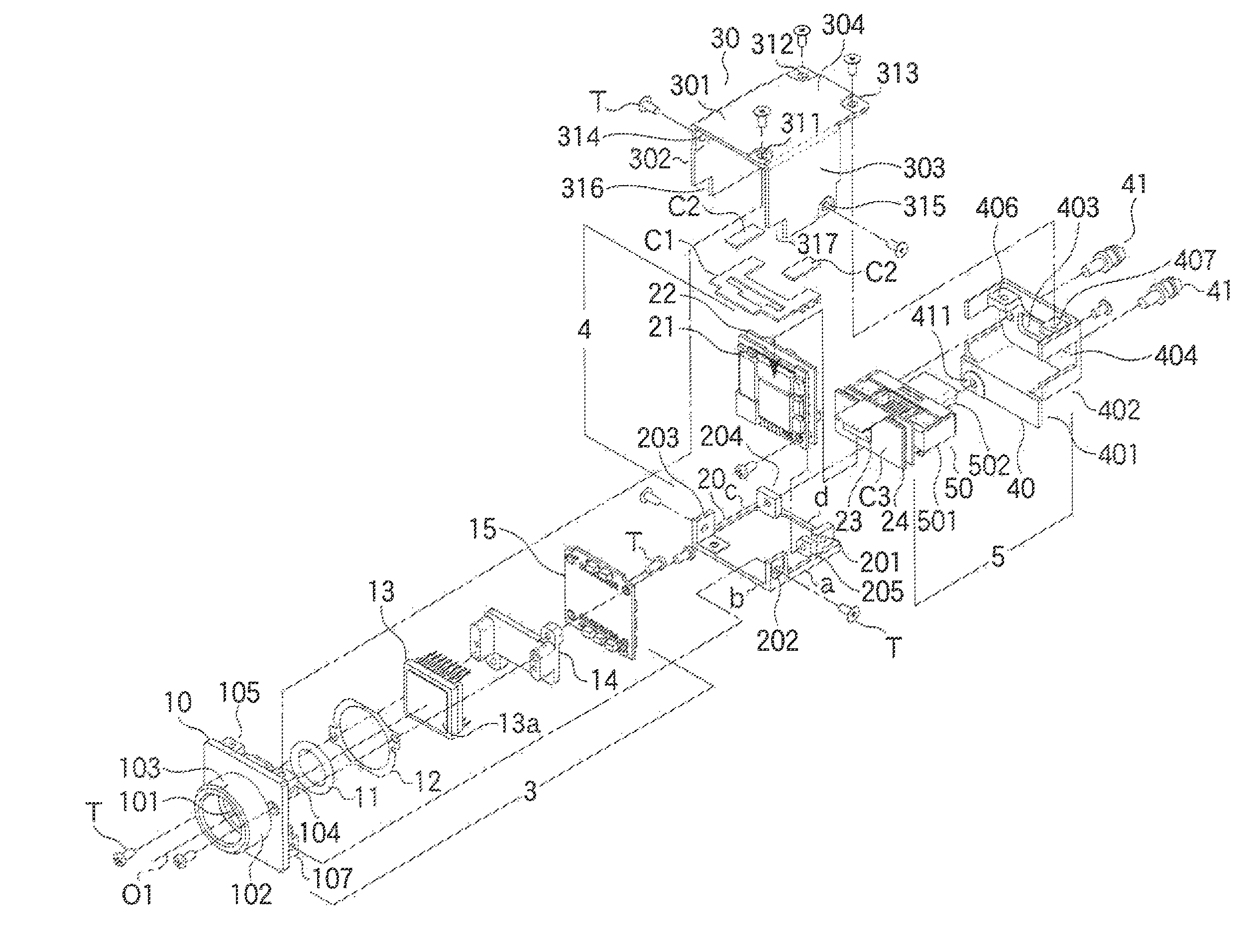
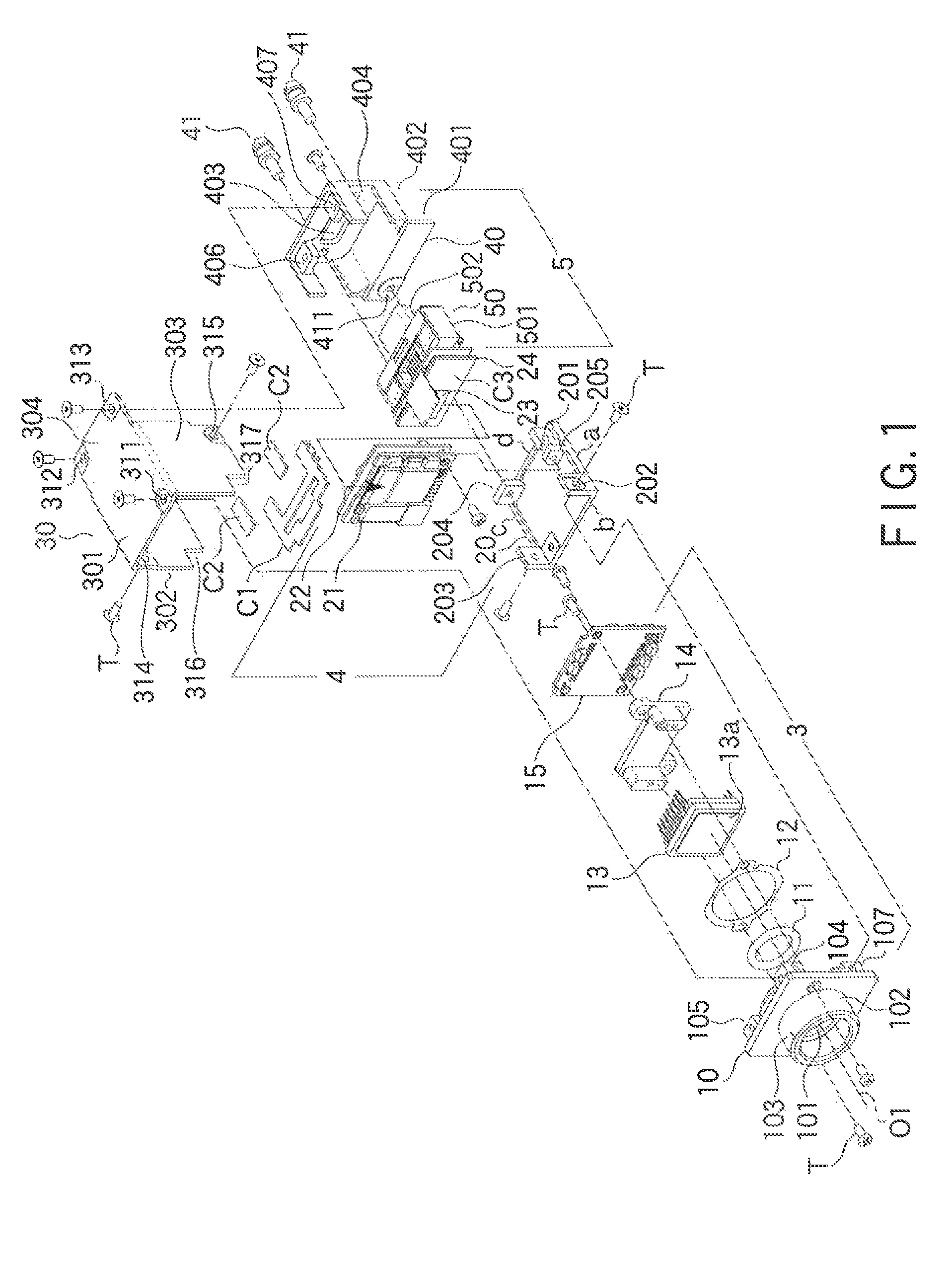
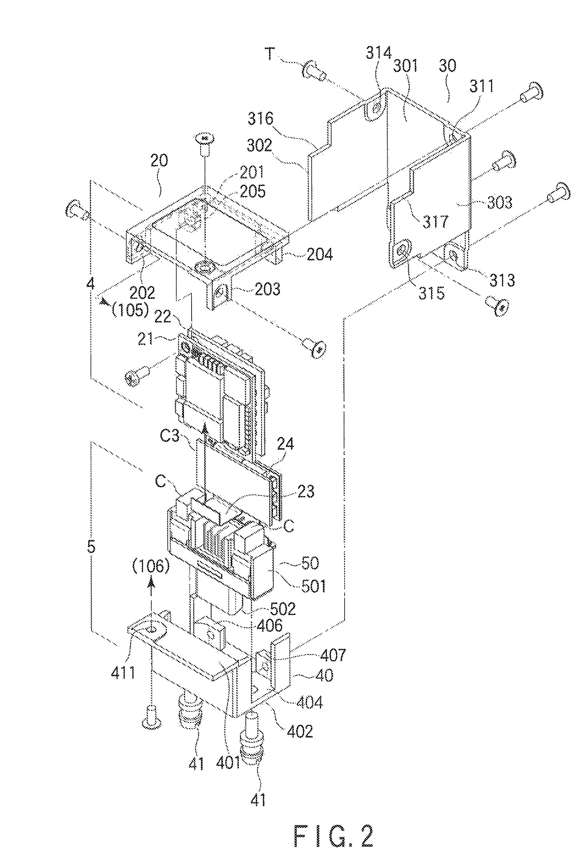
[0058]FIGS. 1, 2, 3A, and 4A show a camera assembly structure of a small industrial electronic imaging camera according to an embodiment of the invention. FIG. 1 (exploded perspective view) and FIG. 3A (side cross-sectional view) show the assembly structure when an external interface connector is provided at a back face part (rear face part) of a box-type camera housing having a hexahedral structure, to lead an external interface cable from the back face part of the box-type camera housing. FIG. 2 (partial exploded perspective view) and FIG. 3A (side cross-sectional view) show an assembly structure when an interface connector is provided at an arbitrary side face part (any one of upper, lower, left, and right face parts) of the box-type camera housing, to lead an external interface cable from the side face part of the box-type camera housing. In the following, the camera assembly struc...


PUM


Abstract

A box-type camera housing having a four-piece structure which allows an external interface connector to be provided in an arbitrary face among five faces except a front face is configured by a lens mount, a board mount frame, a tri-face cover, and a connector metal bracket attached with an external interface connector. In addition, the camera functions are integrated by containing, in an imaging chamber in the camera housing, a control board for controlling a sensor substrate and a power supply board for controlling supply of an operation power for the sensor board and control board, in addition to a sensor board.

Description

CROSS REFERENCE TO RELATED APPLICATIONS[0001]This application is a Continuation Application of PCT Application No. PCT / JP2010 / 072800, filed Dec. 17, 2010 and based upon and claiming the benefit of priority from prior Japanese Patent Application No. 2009-296194, filed Dec. 25, 2009, the entire contents of all of which are incorporated herein by reference.BACKGROUND OF THE INVENTION[0002]1. Field of the Invention[0003]The present invention relates to a small industrial electronic imaging camera comprising a connection mechanism for connecting an external interface cable, which is preferably applied to a machine vision system.[0004]2. Description of the Related Art[0005]In a small electronic imaging camera having a box type housing structure having edges which are, for example, about 20 to 30 mm long, i.e., a so-called microcamera in a machine vision system, a large pace is occupied by external interface connectors in the housing, and therefore, there is a difficulty in maintaining spa...

Claims


Application Information

Patent Timeline
Patent Type & Authority Patents(United States)
IPC IPC(8): H04N5/225
CPCH04N5/2252H04N23/51G03B17/02
Inventor HASEGAWA, NAOSHIHONMA, SHUJIASAMI, SAYAKAYAMAGUCHI, MASAYOSHIHARADA, EIICHI
Owner TOSHIBA TELI CORP
Why Eureka
Try Eureka