Liquid ejecting head unit and liquid ejecting apparatus

a liquid ejecting head and liquid ejecting technology, which is applied in the direction of printing, inking apparatus, etc., can solve the problems of troublesome disassembly and reassembly of such wiring members or in inferior conta

Active Publication Date: 2012-05-01
SEIKO EPSON CORP
View PDF1 Cites 0 Cited by
  • Summary
  • Abstract
  • Description
  • Claims
  • Application Information

AI Technical Summary

Benefits of technology

[0006]An advantage of some aspects of the invention is that it solves the above-mentioned technical problems of the related art and provides a liquid ejecting head unit with high general versatility in which a head can be relatively easily replaced by the user and which does not cause inferior contact during the replacement procedure, and a liquid ejecting apparatus employing the liquid ejecting head unit.
[0008]According to an aspect of the invention, attachment and detachment of the wiring member from the liquid ejecting head body become easier by using the connector member, and the user may relatively readily replace the head. Since the wiring member inserted into the wiring member connector of the connector member is retained between the retaining member and the base member in the folded state, no inferior contact is caused as a result of the replacement procedure.
[0011]It is also preferable that a first sealing member for sealing the connecting section with the wiring member be provided on at least one of the abutment surfaces between the base member and the retaining member. In this structure, the connecting section of the wiring member is sealed in the space between the base member and the protecting member, thus preventing mist-like liquid from entering the space.
[0012]It is also preferable that the retaining member be made from a transparent member. In this structure, the connecting section of the wiring member may readily be checked visually, thus preventing inferior connection or the like in advance.
[0013]It is also preferable that a second sealing member for sealing the connecting section between the first connector section and the second connector section be provided on at least one of the abutment surfaces around the first connector section of the liquid ejecting head body or around the second connector section of the base member. In this structure, the connecting section between the first connector section and the second connector section is sealed by the second sealing member, thus preventing mist-like liquid from entering.
[0016]According to this aspect, attachment and detachment of the wiring members from the liquid ejecting head body become easier by using the connector member, and the liquid ejecting apparatus for which the user may relatively readily replace the head may be attained. Since the wiring members inserted into the wiring member connector of the connector member are retained between the retaining member and the base member in the folded state, no inferior contact is caused during the replacement procedure.

Problems solved by technology

While it is plausible that a user can replace a single head that has been damaged in the above-mentioned liquid ejecting head unit, wiring members for supplying drive signals or the like to respective heads are connected to the respective heads, and problems lie in troublesome disassembly and reassembly of such wiring members or in inferior contact after reconnection.

Method used


Image

  • Liquid ejecting head unit and liquid ejecting apparatus
  • Liquid ejecting head unit and liquid ejecting apparatus
  • Liquid ejecting head unit and liquid ejecting apparatus

Examples


Embodiment Construction

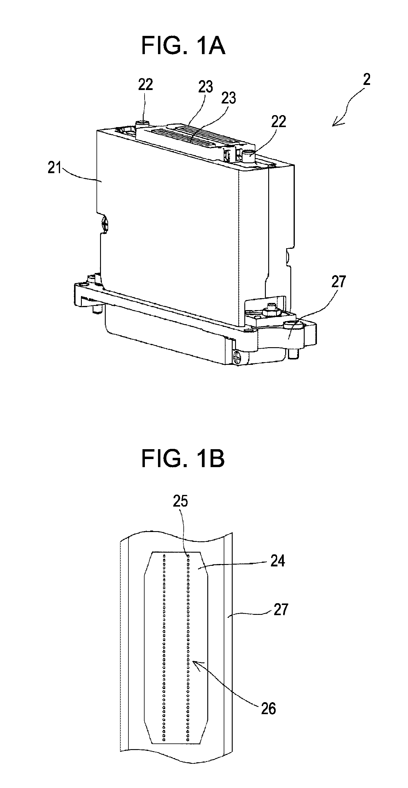
[0030]First, the ink jet recording head 2 (hereinafter simply referred to as the ‘head’) used for the ink jet recording head unit 1, which is a liquid ejecting head unit according to the invention (hereinafter simply referred to as the ‘head unit’), is described below with reference to FIG. 1. FIG. 1 is used to explain the structure of the head. FIG. 1A is a perspective view of the head, and FIG. 1B is a bottom view of the major sections of the head.

[0031]Each of the heads 2 is equipped with a head body 21 for ejecting ink from a nozzle opening in response to an incoming drive signal. An end surface (upper end surface) of the head body 21 is provided with ink intake ports 22 for introducing ink into the head body 21, and two first connectors 23 to which connector members to be mentioned below are connected for entering drive signals. While two ink intake ports 22 are provided in the current embodiment, only one ink intake port 22 may be sufficient. Nozzle openings 25 for ejecting in...


PUM


Abstract

A liquid ejecting head unit including liquid ejecting head bodies for ejecting liquid by the drive of a pressure generating device; wiring members for feeding drive signals to the pressure generating device of the liquid ejecting head bodies; and connector members provided at an end of the wiring members, being connected by the wiring members, and having second connector sections detachable from first connectors of the liquid ejecting head bodies; wherein the connector members respectively include a base member equipped with a wiring member connector for inserting the connecting end of the wiring member for connection, and a retaining member fixed to the base member covering the wiring member connector section; wherein the wiring members inserted into the wiring member connector are retained in a folded state by the retaining members.

Description

BACKGROUND[0001]1. Technical Field[0002]The present invention relates to a liquid ejecting head unit and a liquid ejecting apparatus.[0003]2. Related Art[0004]An existing liquid ejecting apparatus typified by an ink jet recording apparatus such as an ink jet printer includes a liquid ejecting head unit having a plurality of liquid ejecting heads capable of ejecting liquid such as ink stored in a cartridge, tank or the like in the form of droplets. A unit in which a plurality of liquid ejecting heads are fixed on a common retaining member or a base plate in alignment in one direction and in a state of being slightly staggered in the other direction is known as such a liquid ejecting head unit (refer to JP-A-2000-25207 as an example).[0005]While it is plausible that a user can replace a single head that has been damaged in the above-mentioned liquid ejecting head unit, wiring members for supplying drive signals or the like to respective heads are connected to the respective heads, and...

Claims


Application Information

Patent Timeline
Patent Type & Authority Patents(United States)
IPC IPC(8): B41J2/14
CPCB41J2/155B41J2202/08B41J2202/20B41J2202/19B41J2202/14
Inventor SUZUKI, SHIGEKIOGUCHI, SATOSHI
Owner SEIKO EPSON CORP
Why Eureka
Try Eureka