Thin display apparatus

a display apparatus and thin technology, applied in the direction of television systems, electric apparatus casings/cabinets/drawers, instruments, etc., can solve the problems of excessively high temperature of the disk drive unit itself, poor ventilation of the thin display apparatus, and easy dust on the disk drive unit, etc., to achieve the effect of improving the appearance and reducing the thickness

Inactive Publication Date: 2013-12-10
SHARP KK
View PDF16 Cites 0 Cited by
  • Summary
  • Abstract
  • Description
  • Claims
  • Application Information

AI Technical Summary

Benefits of technology

[0010]Moreover, countermeasures against heat of a disk drive unit are preferred to be achieved by a structure as simple as possible. Furthermore, a disk drive unit is easily affected by dust, and it is therefore not preferable to employ an air cooling structure using the external air flowing in.
[0011]The present invention has been made on the basis of the above circumstances, and its object is to provide a thin display apparatus which controls rise in temperature of a disk drive by heat-transfer from high temperature internals of the apparatus by a simple configuration.
[0015]According to the present invention, an area of the thermal insulating recess sealed by the disk drive unit becomes a thermal insulating layer between the rear side casing and the disk drive unit, and the thermal insulating layer interrupts thermal transfer from the high temperature internals of the apparatus to the disk drive unit.
[0016]In addition, the disk drive unit also functions as a sealing member for the thermal insulating recess, and by only mounting the disk drive unit on the rear side casing, the thermal insulating layer is formed. The simple configuration realizes countermeasures against heat of the disk drive unit.
[0024]This allows the covering member integrated with the disk drive unit to be fitted in the fitting recess and be positioned, and at the same time the disk drive unit to be positioned with respect to the thermal insulating recess. As a result, this facilitates the mounting of the disk drive unit and the covering member on the rear side casing. Additionally, a mechanism of fitting the covering member in the fitting recess makes it difficult for outside dust to enter into the disk drive unit.
[0025]According to the present invention, a thin display apparatus can control rise in temperature of a disk drive by heat-transfer from high temperature internals of the apparatus with a simple configuration.

Problems solved by technology

A thin display apparatus therefore generally has poor ventilation, with the component density therewithin enhanced by the thickness reduction.
However, in a particularly-thin display apparatus, mounting of a disk drive unit on a casing on the rear side whose temperature rises very high may result in an excessively high temperature of the disk drive unit itself.
Furthermore, a disk drive unit is easily affected by dust, and it is therefore not preferable to employ an air cooling structure using the external air flowing in.
Additionally, a mechanism of fitting the covering member in the fitting recess makes it difficult for outside dust to enter into the disk drive unit.

Method used


Image

  • Thin display apparatus
  • Thin display apparatus
  • Thin display apparatus

Examples


Embodiment Construction

[0031]The present invention now will be described more fully hereinafter with reference to the accompanying drawings illustrating embodiments thereof. Additionally, the following embodiment is merely an embodied example of the present invention which should not limit the technical scope of the present invention.

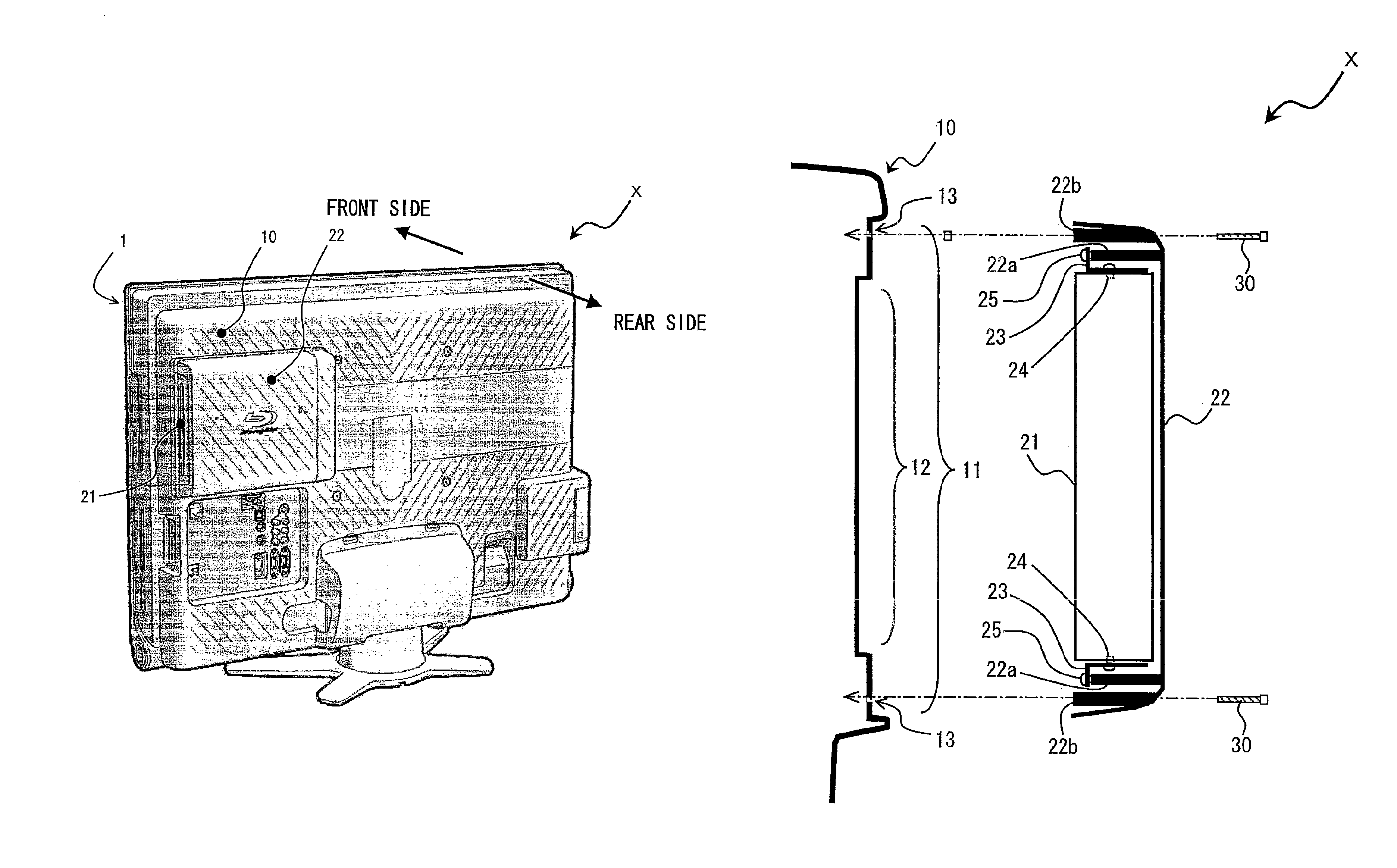
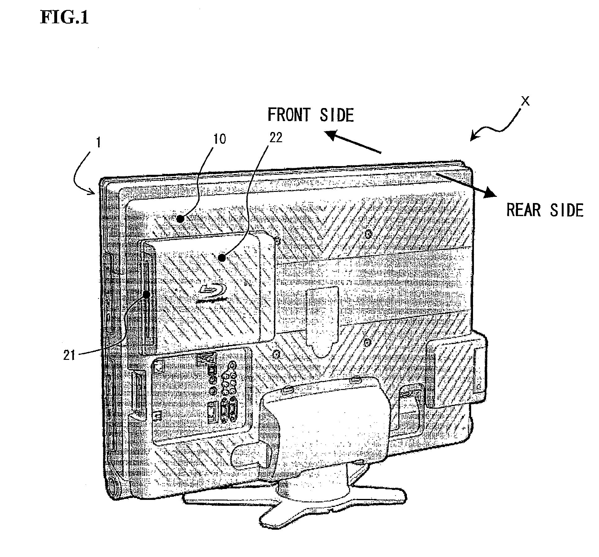
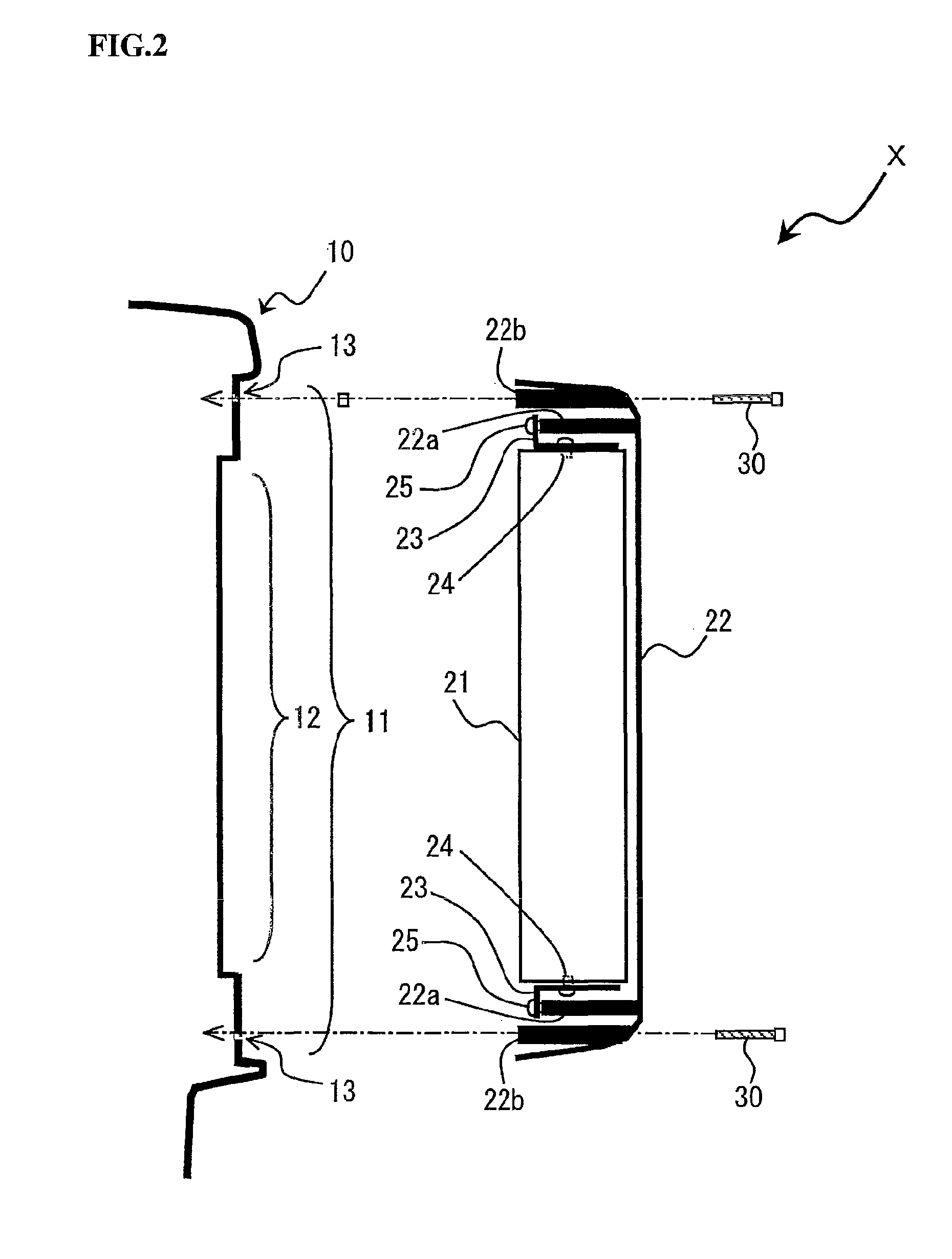
[0032]FIG. 1 is a perspective view viewed from a rear side of a liquid crystal television receiver X as an example of a thin display apparatus according to an embodiment of the present invention; FIG. 2 is a cross sectional view showing an assembly structure of a disk drive in the liquid crystal television receiver X; FIG. 3 is a view showing a position of a disk drive arranged on a rear side casing of the liquid crystal television receiver X; FIG. 4 is a cross sectional view showing a thermal insulation structure of a disk drive in the liquid crystal television receiver X.

[0033]Referring now to a perspective view of FIG. 1, an appearance of a liquid crystal television receiv...


PUM

PropertyMeasurementUnit
thicknessaaaaaaaaaa
thermal insulationaaaaaaaaaa
areaaaaaaaaaaa

Abstract

A thin display apparatus equipped with a video display panel controls rise in temperature of a disk drive by heat-transfer from high temperature internals of the apparatus. A thermal insulating recess is formed in a face of a rear side casing which faces a disk drive unit, and a surface of the disk drive unit mounted on the rear side casing seals the thermal insulating recess. An area of the thermal insulating recess sealed by the disk drive unit becomes a thermal insulating layer between the rear side casing and the disk drive unit, and the thermal insulating layer interrupts thermal transfer from the high temperature internals of the apparatus to the disk drive unit.

Description

[0001]This application is the national phase under 35 U.S.C. §371 of PCT International Application No. PCT / JP / 2009 / 068870 which has an International filing date of Nov. 5, 2009 and designated the United States of America.BACKGROUND[0002]The present invention relates to a thin display apparatus comprising a video display panel and a disk drive unit mounted outside a rear side casing forming an exterior of a rear side of the video display panel.DESCRIPTION OF RELATED ART[0003]Nowadays, thickness reduction of a thin display apparatus as a panel-type display apparatus comprising a video display panel, such as a liquid crystal panel, has been increasingly advanced, as can be represented by a liquid crystal television receiver. Such a display apparatus generally has a thickness of several tens millimeters. Even one having a thickness of less than 10 millimeters begins to be introduced.[0004]A thin display apparatus therefore generally has poor ventilation, with the component density there...

Claims


Application Information

Patent Timeline
Patent Type & Authority Patents(United States)
IPC IPC(8): G06F1/16G02F1/1333
CPCG11B31/006G11B33/1406H04N5/64H05K7/20963H05K5/02
Inventor MATSUI, YOSHITAKAMATSUYA, KATSUHIKO
Owner SHARP KK
Why Eureka
Try Eureka