Current trigger circuit and switching power converter using the same

a current trigger circuit and current trigger technology, applied in the direction of ignition automatic control, process and machine control, instruments, etc., can solve the problems of circuit with high conversion efficiency and easy failure of detection, and achieve the effect of reducing power consumption, increasing conversion efficiency, and easy affecting

Active Publication Date: 2010-09-30
GREEN SOLUTION TECH CO LTD
View PDF4 Cites 15 Cited by
  • Summary
  • Abstract
  • Description
  • Claims
  • Application Information

AI Technical Summary

Benefits of technology

[0007]Accordingly, comparison of the voltage difference with the reference voltage is easily affected by noises in the related art while detecting the current. In the present invention, a voltage difference in a detecting element is compared with a bias voltage, so that the above-described issue is avoided. Accordingly, it is able to decrease power consumption arisen from current detection and to further increase conversion efficiency.

Problems solved by technology

As a result, the detection easily fails, and the erroneous operation is induced.
How to provide a detecting circuit with high conversion efficiency thus becomes an inevitable issue in compliance with the current trend that the operation voltages of the electric elements become lower and lower.

Method used


Image

  • Current trigger circuit and switching power converter using the same
  • Current trigger circuit and switching power converter using the same
  • Current trigger circuit and switching power converter using the same

Examples


Embodiment Construction

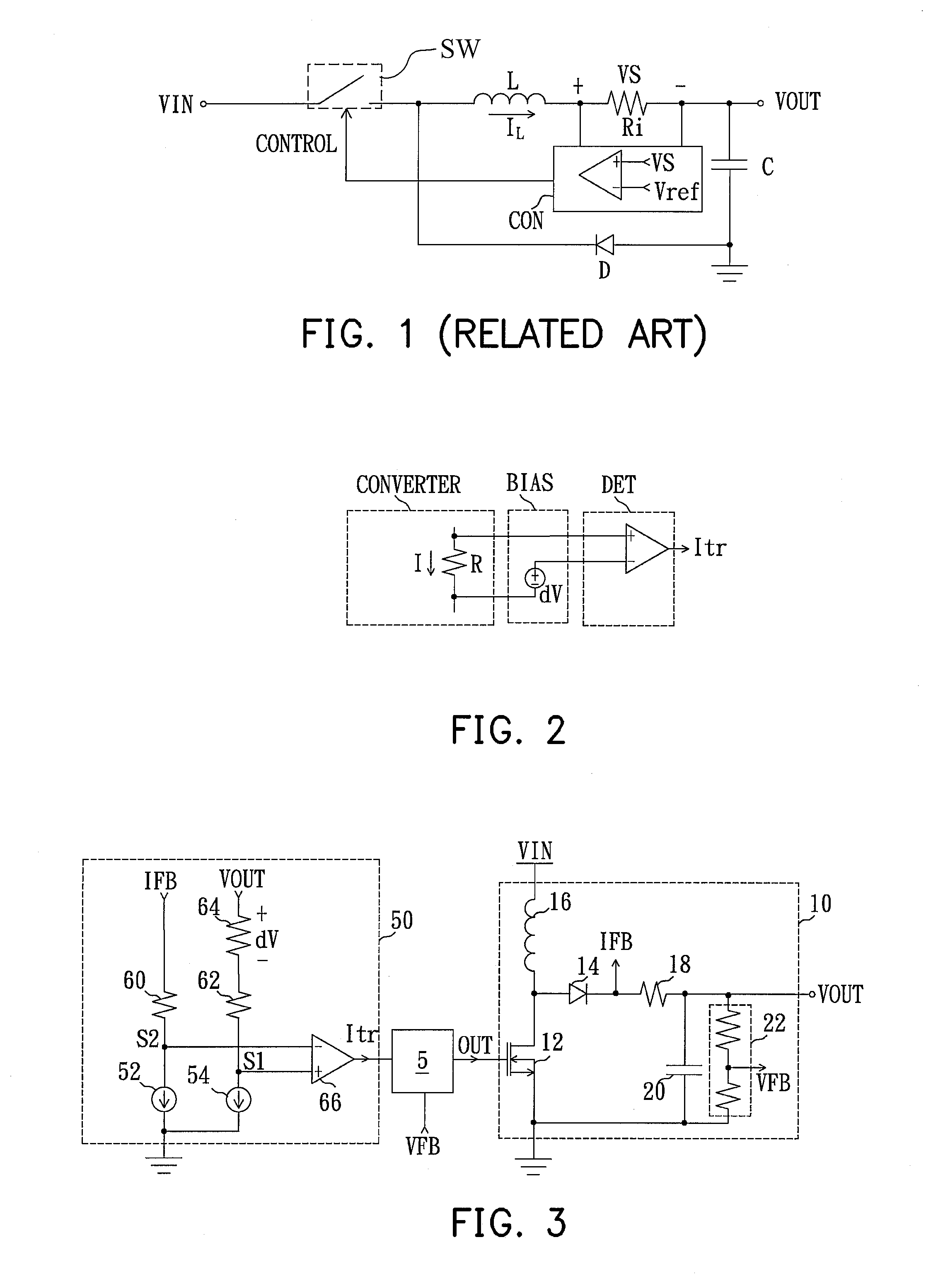
[0019]Please refer to FIG. 2, which is a schematic diagram of a current trigger circuit according to an exemplary embodiment consistent with the present invention. The converting circuit CONVERTER has a detecting resistor R, which a current I passes through. A bias voltage unit BIAS has a first detecting end and a second detecting end respectively coupled to two terminals of the detecting resistor R. In addition, the bias voltage unit BIAS provides a bias voltage dV to one of the first detecting end and the second detecting end. A trigger unit DET is coupled to the bias voltage unit BIAS. While a voltage difference I*R across the detecting resistor R is raised up to a level higher than the bias voltage dV, the trigger unit DET immediately generates a current trigger signal Itr with a high level. Since noise interferences from circuits of the first detecting end and the second detecting end coupled to the trigger unit DET are mutually offset, current detection is almost not affected ...


PUM


Abstract

A bias voltage is compared with a voltage difference in a detecting element according to the present invention. A bias voltage unit is coupled to the detecting element, so that they have a common voltage level to avoid noises when the circuit is operating. Accordingly, the erroneous detection caused by the noise interference can be avoided. Hence, a detecting element with a low resistance, such as an MOEFET, can be used in the present invention to decrease power consumption arisen from current detection and to further increase conversion efficiency.

Description

CROSS-REFERENCE TO RELATED APPLICATION[0001]This application claims the priority benefit of Taiwan application serial no. 098109814, filed on Mar. 26, 2009. The entirety of the above-mentioned patent application is hereby incorporated by reference herein and made a part of specification.BACKGROUND OF THE INVENTION[0002]1. Field of the Invention[0003]The present invention generally relates to a switching power converter and a current trigger circuit, and more particularly, to a switching power converter and a current trigger circuit capable of comparing a bias voltage with a voltage difference in a detecting element to detect a current flowing through the detecting element.[0004]2. Description of Related Art[0005]Please refer to FIG. 1, which is a schematic diagram of a buck DC / DC converting circuit for converting an input voltage VIN to an output voltage VOUT in a related art. The buck DC / DC converting circuit includes a switch SW, an inductor L, a capacitor C, a diode D, a detectin...

Claims


Application Information

Patent Timeline
Patent Type & Authority Applications(United States)
IPC IPC(8): G05F1/10
CPCH02M2001/0009H02M3/156H02M1/0009
Inventor CHEN, JI-MINGCHIEN, HUAN-WEN
Owner GREEN SOLUTION TECH CO LTD
Why Eureka
Try Eureka