High efficiency single stage bidirectional converter

a converter and single-stage technology, applied in the field of dcdc conversion technology, can solve the problems of reducing efficiency substantially, increasing the complexity of the driving circuit, and large size of the conventional system, and achieve the effect of boosting the voltage of the dc input source v1, preventing the damage of circuit components, and stable dc output voltage vo

Inactive Publication Date: 2008-05-20
YUAN ZE UNIV
View PDF5 Cites 16 Cited by
  • Summary
  • Abstract
  • Description
  • Claims
  • Application Information

AI Technical Summary

Benefits of technology

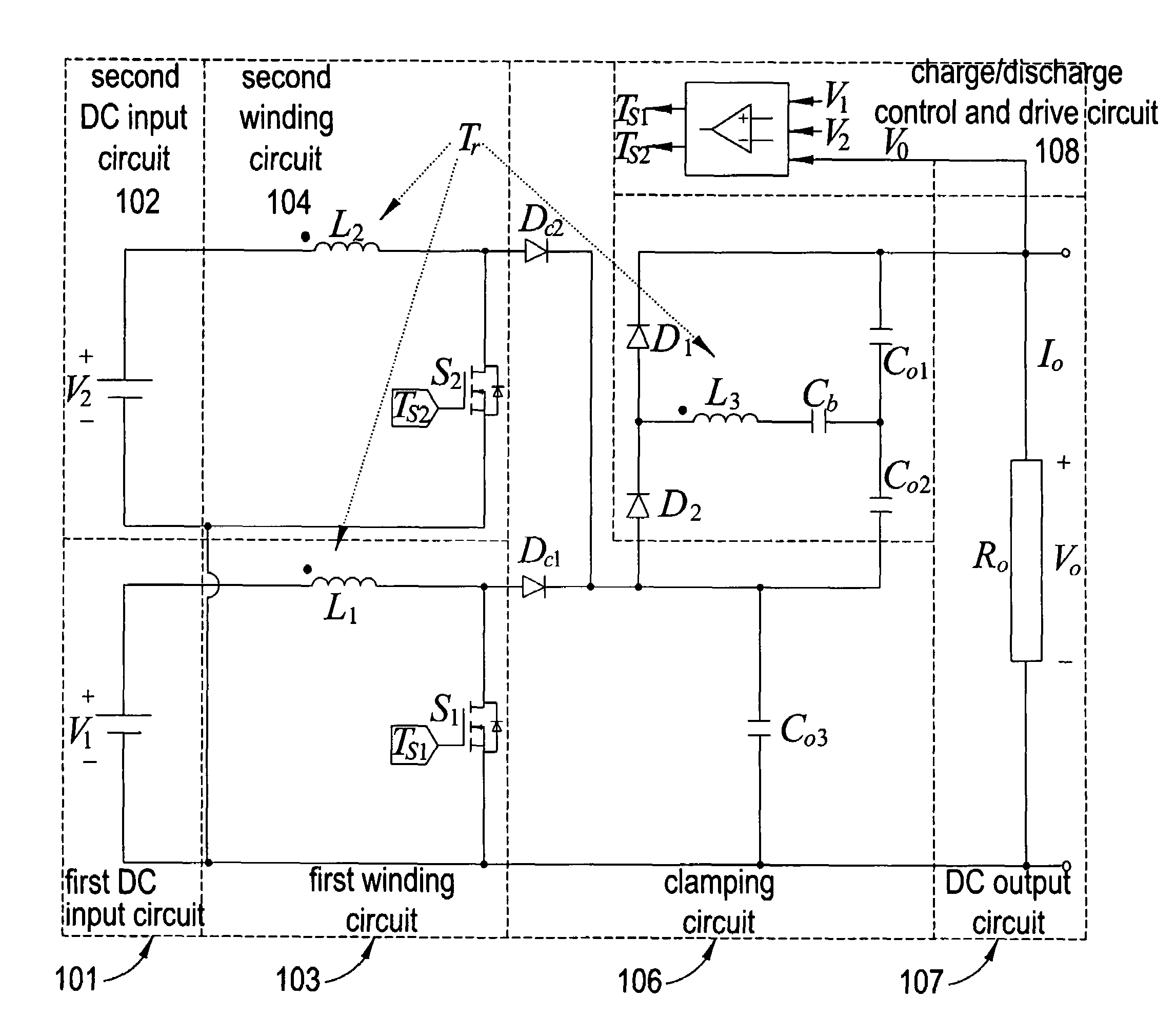
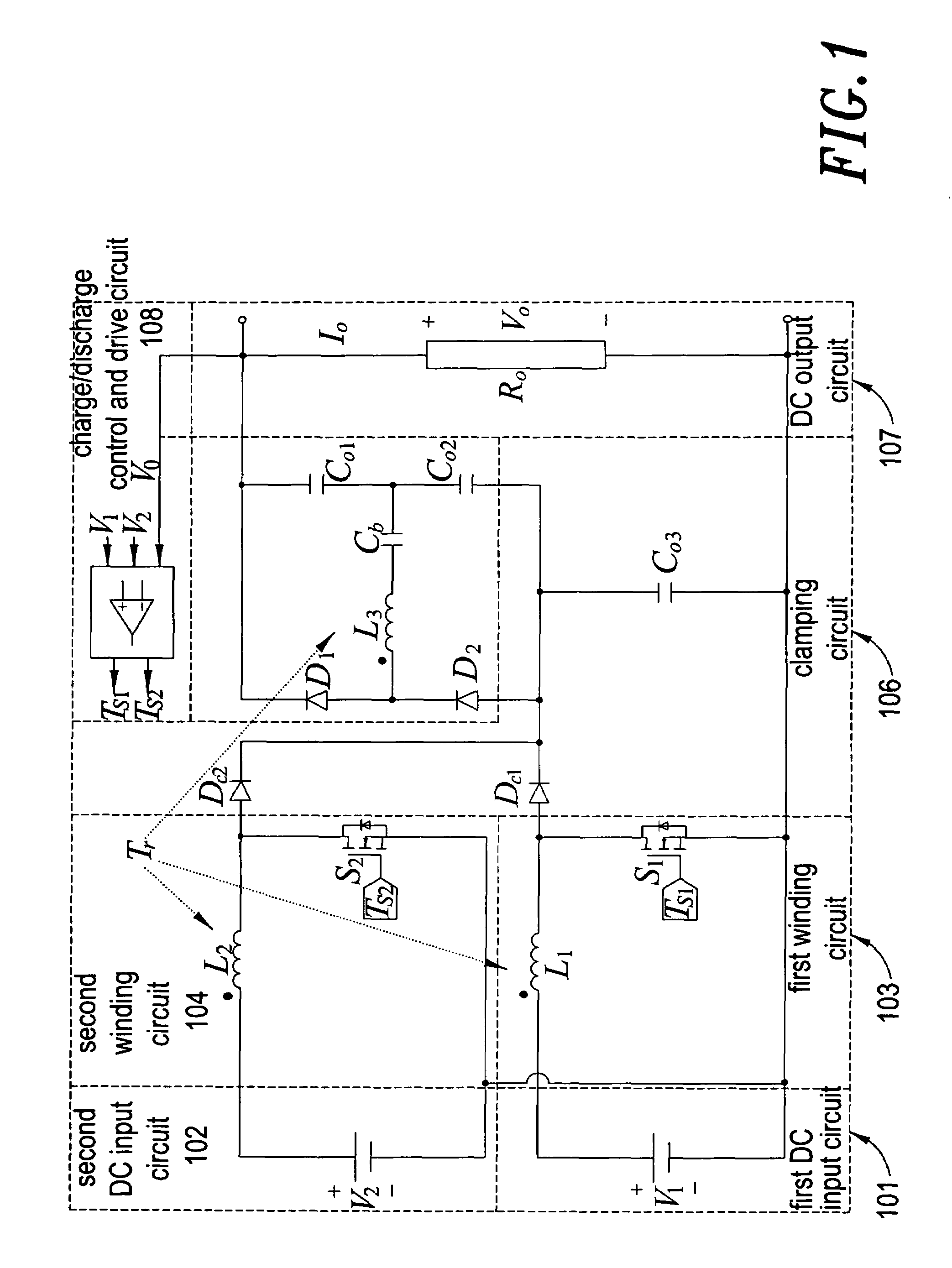
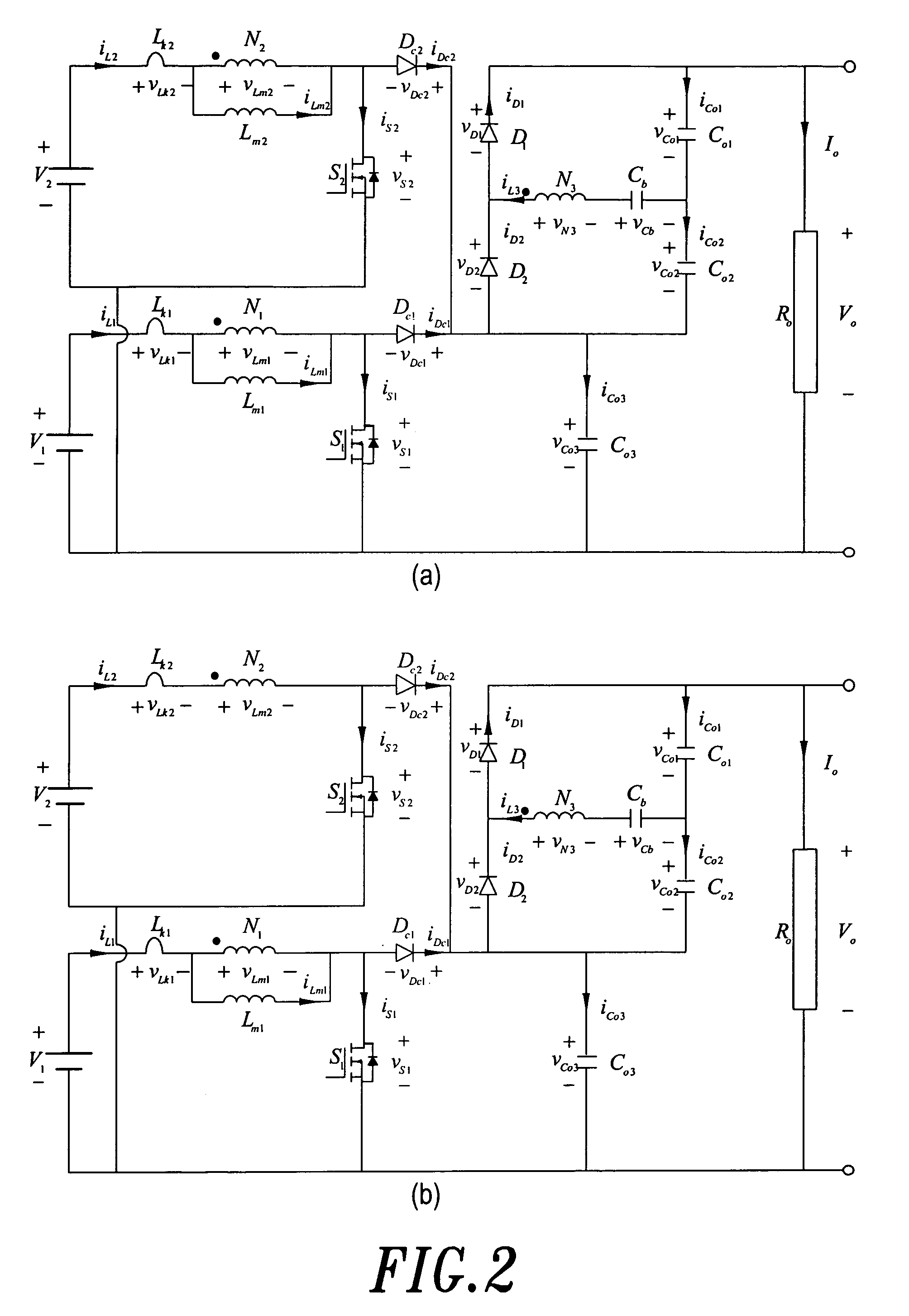
[0022]Other than using the first DC input voltage source V1, through a high efficiency single-stage multi-input bi-directional converter, to greatly boost the voltage of the DC input source V1 and supply the power to the load Ro, the present invention also can use the first DC input source V1 to directly charge the second DC input source V2; when the first power semiconductor switch S1 of first winding circuit 103 is turned on, the first winding induction Lm1 establishes voltage in each winding and stores energy; at the same time, the polar terminal of the second winding L2 has a positive voltage, and the second power semiconductor switch S2 of second winding circuit 104 is turned on and charges the second DC input voltage source V2, where the second power semiconductor switch S2 has a synchronous rectification effect. Moreover, the polar terminal of the third winding L3 has a positive voltage, and through the first high voltage diode D1 of third winding circuit 105, charges the first high voltage capacitor Co1; at the moment, the current iL2 and iL3 of the second and third winding are provided by the current iL1 of the first winding; when the first power semiconductor switch S1 is turned off, and the first clamping diode Dc1 of clamping circuit 106 is turned on and charges the clamping capacitor Co3, absorbing energy released by the first winding leakage induction Lk1 and preventing circuit components damaged by voltage spike; in addition, after the third winding current iL3 reverses direction, according to flux conservation theory, the energy stored in the first winding induction Lm1 converts to induction energy in the third winding L3 for charging the second high voltage capacitor Co2 of third winding circuit 105; by adding the voltages of the first high voltage capacitor Co1, the second high voltage capacitor Co2 and the clamping capacitor Co3, a stable DC output voltage Vo is obtained.
[0023]In the standalone state, the present invention uses the first DC input voltage source V1 and on / off of the first power semiconductor switch S1 of first winding circuit 103, through a high efficiency single-stage multi-input bi-directional converter, to substantially boost the voltage of the DC input source V1 and supply the power to the load Ro; when the first power semiconductor switch S1 of first winding circuit 103 is turned on, the first winding excited induction Lm1 establishes voltages of each winding and stores energy; the polar terminal of third winding L3 has positive voltage, causing the first high voltage diode D1 of third winding circuit 105 to turn on and further charging the first high voltage capacitor Co1, where the third winding current iL3 is also provided by the first winding current iL1; when the first power semiconductor switch S1 is turned off, the first clamping diode Dc1 of the clamping circuit 106 is turned on and charges the clamping capacitor Co3, absorbing energy released by the first winding leakage induction Lk1 of coupled inductor; at the same time, according to flux conservation theory, energy stored in the first winding excited induction Lm1 is converted to energy of the third winding L3 for charging the second high voltage capacitor Co2; by adding the voltages of the first high voltage capacitor Co1, the second high voltage capacitor Co2 and the clamping capacitor Co3, a stable DC output voltage Vo is obtained.

Problems solved by technology

Clean energy source becomes an important subject due to oil shortage crisis.
However, one of the converters has to be able to function in bi-direction for charging the rechargeable battery; the energy needed for charging is from clean energy source and this energy has to be converted many time before reaching the rechargeable battery, therefore reducing efficiency substantially.
Overall, conventional system is large in size, complex in structure and expensive [2].
This control method also makes driving circuit more complex; and under impact of duty cycles being divided, each power source has fewer duty cycles, decreasing voltage gain of the converter.
In addition, adding diode in main passage of power supply will increase conduction loss for a clean energy source with of low voltage / large current character, and decrease conversion efficiency; also, it will prevent possibility of charging route and is not well suit for clean energy source applied in distributed power generating system.
However, the main route also has several diodes and excessive number of switches, making charging route impossible; this will mandate additional charging circuit and make the structure more complex and less efficient.
Due to its electrical characteristics of low voltage and large current as well as high output voltage, clean energy source is large in size and difficult to make; its output voltage fluctuates easily with load variation.
Also, high voltage rechargeable battery made up of multiple stacked batteries is not reliable, making it more appealing to have multiple-input converter with high voltage boost gain for applications which require high voltage.
However, maximum voltage boost gain of this kind of structure only equals to winding ratio, and output rectifying diode has to bear at least twice of output voltage; to high output voltage, it is hard to find qualified diode.
The coupled inductor structure can not only provide higher voltage boost ratio, but also reduces voltage burden on switches and reversal-recovery current of the diode.
For voltage boost using coupled inductor, the key technique leis in processing of leakage induction energy; if not processed properly, it will cause high voltage spikes, increasing conducting loss and necessitate higher voltage bearing on the switches.

Method used


Image

  • High efficiency single stage bidirectional converter
  • High efficiency single stage bidirectional converter
  • High efficiency single stage bidirectional converter

Examples


Embodiment Construction

[0134]In the high efficiency single-stage multi-input bi-directional converter of the present invention, first CD input voltage source V1 is PowerPEMTM-PS250 fuel cell battery made by H-Power Co., its specified power is 250 W and its characteristic is shown in FIG. 10. To have the embodiment fully elaborate aforementioned theoretical analysis, depending on each state, first DC input voltage source V1 is chosen as its power P1d=250 W, corresponding voltage V1d=29.6V; power P1c=165 W, and corresponding voltage V1c=31.5V. In addition, two group 12V rechargeable batteries connected in series to form a 24V rechargeable battery is chosen as second DC input voltage source V2. When power needed by a load Ro exceeds the specified power P1d=250 W, the rechargeable battery provides power P2d to the load Ro, and this is the discharging state; when the load Ro need smaller power, the rechargeable battery is charged, in which the power used by the load Ro plus the battery charging power P2c are p...


PUM


Abstract

The present invention focuses on the development of a high-efficiency single-stage bidirectional converter with multi-input power sources. In the present invention, it takes a three-winding coupled inductor as the main component of energy transmission, and utilizes only two power semiconductor switches to accomplish the multi-input function. According to the designed switching conditions, this circuit could be operated at discharge, charge and standalone states to simplify conventional structure in which multiple converters are used in boosting voltage and then connected in parallel to supply power. Moreover, the coupled inductor as the principal part of this circuit has high-voltage gain property, and the present invention fully utilizes the winding voltage in the high-voltage side to further increase the corresponding voltage gain superior to that in the conventional coupled-inductor strategy. This property is helpful to solve the power conversion problem caused by clean energies with inherent low-voltage characteristics. In addition, all switches and diodes have favorable voltage-clamped effects so that the voltage spikes induced by the leakage-induction energy can be alleviated effectively, and there are no high reverse-recovery currents within diodes because the leakage induction can restrain instantaneous changes in the current. Furthermore, the present invention has a charging route of low-voltage conversion without adding additional components, avoiding the power losses induced by the multistage conversion in the traditional auxiliary power systems, and utilizes the synchronous rectification technique to decrease the conducting losses.

Description

BACKGROUND OF THE INVENTION[0001]1. Field of the Invention[0002]The present invention is related to DC-DC conversion technology, specifically, using clean energy in a distributed electrical generating system, and utilizing rechargeable batteries as auxiliary power source, in which multiple inputs mechanism, charging loop of low voltage conversion, voltage clamping and synchronous rectification technique are used to overcome the drawback in existing clean energy used in the distributed electrical generating system.[0003]2. Description of the Prior Art[0004]Clean energy source becomes an important subject due to oil shortage crisis. Clean energy source, such as fuel cell battery, solar battery, can be used in a distributed power generation equipment, including electrical transportation equipment, un-interrupted electrical power system and standalone electrical power generating system, etc. In a distributed power generating system in which clean energy source is used, normally recharge...

Claims


Application Information

Patent Timeline
Patent Type & Authority Patents(United States)
IPC IPC(8): H02M3/335
CPCH02J7/0013H02M1/10H02M3/1584H02J7/0054Y02E70/40H02J2007/0059H02J2207/20H02J7/342Y02E60/10Y02E60/13
Inventor WAI, RONG-JONGLIU, LI-WEI
Owner YUAN ZE UNIV
Why Eureka
Try Eureka