Low floor vehicle

a technology of low-floor vehicles and lateral pressure, applied in the direction of locomotives, rail engaging elements, transportation and packaging, etc., can solve the problems of increasing lateral pressure of vehicles, vibration and creaking sounds in vehicles, and affecting bogies that are not easily affected by bogies, so as to prevent vibration and creaking sounds of vehicles, less easily affect bogies, and reduce lateral pressure applied to vehicles

Inactive Publication Date: 2011-10-06
MITSUBISHI HEAVY IND LTD
View PDF13 Cites 17 Cited by
  • Summary
  • Abstract
  • Description
  • Claims
  • Application Information

AI Technical Summary

Benefits of technology

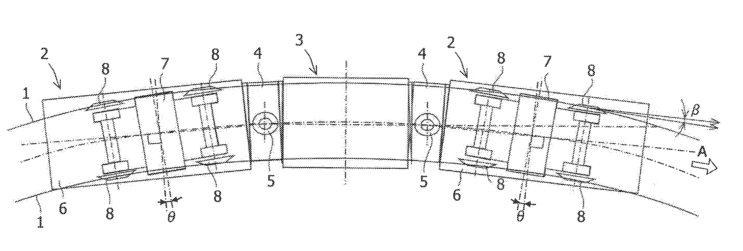
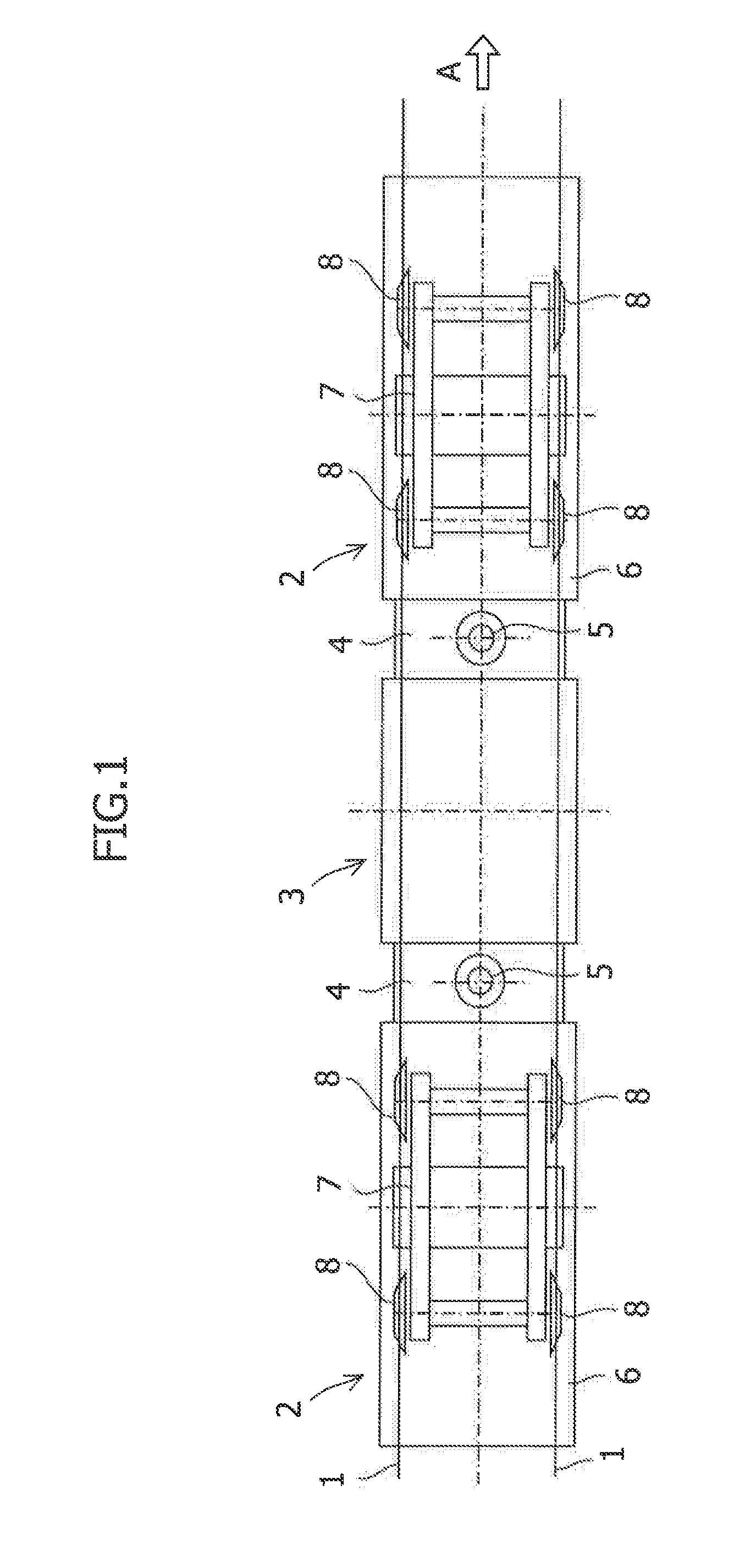
[0014]According to the present invention, effects explained below can be obtained. A low floor vehicle of the present invention is a low floor vehicle including: a bogie provided under a vehicle body; a bogie frame configured as a frame member of the bogie; a pair of bogie frame cross beams arranged along a vehicle lateral direction in the middle of a vehicle longitudinal direction of the bogie frame and arranged spaced apart from each other in the vehicle longitudinal direction; and a pair of wheels provided in each of a vehicle front direction and a vehicle rear direction with respect to the pair of bogie frame cross beams of the bogie frame and configured to travel on a track, wherein a pair of flexible traction rods arranged along the vehicle longitudinal direction and configured to be capable of extending and retracting in the vehicle longitudinal direction are provided in the bogie, the pair of flexible traction rods are arranged spaced apart from each other in a vehicle lateral direction, ends of the flexible traction rods are attached to the bogie frame cross beams, the other ends of the flexible traction rods are attached to a receiving section provided in the vehicle body, and the bogie is configured to be capable of turning with respect to the vehicle body.
[0015]Therefore, when the vehicle enters a curved track, if a wheel on an outside rail side of the pair of wheels comes into contact with the track and force directed to the inner side in the vehicle lateral direction is applied to the wheel on the outside rail side, force for turning with respect to the vehicle body acts on the bogie. At this point, one of the pair of flexible traction rods extends and the other of the pair of flexible traction rods retracts, whereby the bogie can turn with respect to the vehicle body. Force directed in a straight forward direction by the inertia of the vehicle body is absorbed by such a turn of the bogie and less easily affects the bogie. The bogie easily curves along the curved track. As a result, the wheel changes to a state more closely along the curved track and the vehicle can enter the curved track at a small attack angle. Therefore, when the vehicle enters the curved track, contact pressure between the wheel on the outside rail side and the track is relaxed, lateral pressure applied to the vehicle is reduced, and occurrence of vibration and creaking sound of the vehicle is prevented. Therefore, riding comfort of passengers is improved and wear of a wheel flange is reduced. In other words, the vehicle can smoothly pass the curved track.
[0016]A low floor vehicle of the present invention is a low floor vehicle including: a bogie provided under a vehicle body; a bogie frame configured as a frame member of the bogie; a pair of bogie frame cross beams arranged along a vehicle lateral direction in the middle of a vehicle longitudinal direction of the bogie frame and arranged spaced apart from each other in the vehicle longitudinal direction; and a pair of wheels provided in each of a vehicle front direction and a vehicle rear direction with respect to the pair of bogie frame cross beams of the bogie frame and configured to travel on a track, wherein one traction rod arranged along the vehicle longitudinal direction in the center in a vehicle lateral direction is provided in the bogie, one end of the traction rod is attached to the bogie frame cross beam, the other end of the traction rod is attached to a receiving section provided in the vehicle body, a restoring rod arranged along the vehicle longitudinal direction and configured to be capable of extending and retracting in the vehicle longitudinal direction is provided at least one of left and right outer sides in the vehicle lateral direction of the traction rod, one end of the restoring rod is attached to the bogie frame cross beam, the other end of the restoring rod is attached to the receiving section provided in the vehicle body, and the bogie is configured to be capable of turning with respect to the vehicle body.
[0017]Therefore, when the vehicle enters a curved track, if a wheel on an outside rail side of the pair of wheels comes into contact with the track and force directed to the inner side in the vehicle lateral direction is applied to the wheel on the outside rail side, force for turning with respect to the vehicle body acts on the bogie. At this point, one of the pair of restoring rods extends and the other of the pair of restoring rods retracts, whereby the bogie can turn around the traction rod with respect to the vehicle body. Force directed in a straight forward direction by the inertia of the vehicle body is absorbed by such a turn of the bogie and less easily affects the bogie. The bogie easily curves along the curved track. As a result, the wheel changes to a state further along the curved track and can enter the curved track at a small attack angle. Therefore, when the vehicle enters the curved track, contact pressure between the wheel on the outside rail side and the track is relaxed, lateral pressure applied to the vehicle is reduced, and occurrence of vibration and creaking sounds of the vehicle is prevented. Therefore, riding comfort of passengers is improved and wear of wheel flanges is reduced. In other words, the vehicle can smoothly pass the curved track.
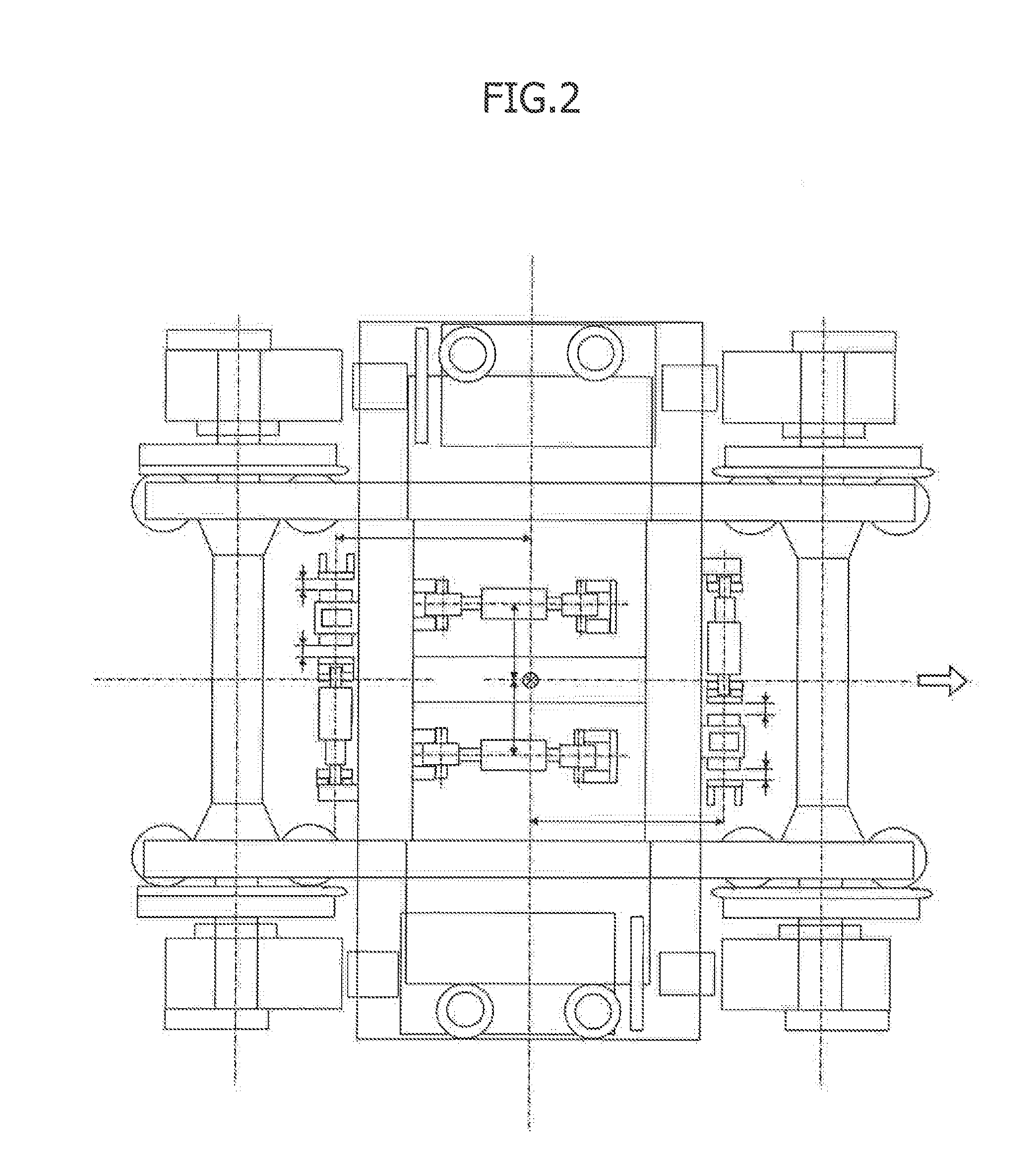
[0018]In the low floor vehicle of the present invention, a turn suppression damper arranged along the vehicle lateral direction and configured to be capable of attenuating force in the vehicle lateral direction is provided in each of a front direction section of the bogie frame cross beam on the vehicle front direction and a rear direction section of the bogie frame cross beam on the vehicle rear direction, one end of the turn suppression damper is attached to the bogie frame cross beam, the other end of the turn suppression damper is attached to the receiving section provided in the vehicle body, and a stopper provided in the vehicle body and a stopper member provided in the bogie are arranged to be capable of coming into contact with each other to regulate a turn of the vehicle body. When external force from the vehicle lateral direction is applied to the vehicle other than the force acting on the bogie from the track when the vehicle enters the curved track as explained above, such external force is attenuated by the turn suppression damper provided on each of the vehicle front direction and the vehicle rear direction. It is possible to prevent the bogie from being turned with respect to the vehicle body by force other than the force acting on the bogie from the track. Therefore, during linear track traveling of the vehicle or the like, the bogie does not turn with respect to the vehicle body and traveling stability of the vehicle is secured. Since a movement amount in the vehicle lateral direction of the bogie is limited by the stopper member, a large turn of the bogie is prevented and traveling stability of the vehicle is further secured. Therefore, it is possible to more surely obtain the effects explained above while securing traveling stability of the vehicle.

Problems solved by technology

However, there is a problem in that, when the vehicle enters a curved track, an angle in a traveling direction of wheels with respect to a tangential direction of the curved track (hereinafter referred to as “attack angle”) increases.
At this point, pressure is applied from the wheel flanges to the vehicle, the lateral pressure of the vehicle increases, and vibration and creaking sounds occur in the vehicle.
As a result, there is a problem in that riding comfort for passengers is degraded and the wheel flanges wear out.
Therefore, force acting on the entire front vehicles 102 is unbalanced.
As a result, there is a problem in that riding comfort of passengers is degraded and the wheel flanges 108b wear out.

Method used


Image

  • Low floor vehicle
  • Low floor vehicle
  • Low floor vehicle

Examples


first embodiment

[0029]A low floor vehicle (hereinafter referred to as “vehicle”) in a first embodiment of the present invention is explained below, in the first embodiment, the vehicle is explained using an LRV as shown in FIG. 1 as an example of the vehicle. In the explanation, it is assumed that a traveling direction of the vehicle is a vehicle front. FIG. 1 is a diagram of the vehicle viewed from above. The traveling direction of the vehicle is indicated by the arrow A. The vehicle shown in FIG. 1 includes two front vehicles 2 and one intermediate vehicle 3 traveling on a track 1. As a vehicle composition, the one intermediate vehicle 3 is arranged between the two front vehicles 2. Connecting sections 4 are provided between the front vehicles 2 and the intermediate vehicle 3. Pin connectors 5 are provided in the connecting sections 4 along an axis extending in a vehicle vertical direction. The front vehicles 2 are coupled to the intermediate vehicle 3 to be capable of turning around the pin conn...

second embodiment

[0046]A vehicle in a second embodiment of the present invention is explained below. In the second embodiment, as in the first embodiment, the vehicle is explained using an LRV as an example of the vehicle. A basic configuration of the vehicle in the second embodiment is the same as the configuration of the vehicle in the first embodiment. Components that are the same as those in the first embodiment are explained using the same reference numerals and signs and names as those in the first embodiment. Components different from those in the first embodiment are explained. In the explanation of the second embodiment, it is assumed that a traveling direction of the vehicle is to the vehicle front.

[0047]The structure of the bogie 7 in the second embodiment is explained with reference to the bogie 7 in a linear traveling time state shown in FIG. 6. One traction rod 21 is provided in the bogie 7. The traction rod 21 is arranged along the axis 8c passing the center between the wheels 8 on th...


PUM


Abstract

A low floor vehicle reduces, when the vehicle enters a curved track, the lateral force of the vehicle, prevents occurrence of vibration and creaking sounds of the vehicle, improves riding quality of passengers, and reduces wear of wheel flanges. A low floor vehicle includes a bogie frame 9 of a bogie 7, a pair of bogie frame cross beams 9a arranged along a vehicle lateral direction in the middle of a vehicle longitudinal direction of the bogie frame 9 and arranged spaced apart from each other in the vehicle longitudinal direction, and a pair of wheels 8 provided in each of a vehicle front edge direction and a vehicle rear edge direction with respect to the pair of bogie frame cross beams 9a of the bogie frame 9 and configured to travel on a track 1. A pair of flexible traction rods 15 arranged along the vehicle longitudinal direction and configured to be capable of extending and retracting in the vehicle longitudinal direction are provided in the bogie 7, the pair of flexible traction rods 15 are arranged spaced apart from each other in a vehicle lateral direction, one ends 15b of the flexible traction rods 15 are attached to the bogie frame cross beams 9a, and the other ends 15c of the flexible traction rods 15 are attached to a receiving section 6c of in the vehicle body 6, and the bogie 7 is configured to be capable of turning with respect to the vehicle body 6.

Description

TECHNICAL FIELD[0001]The present invention relates to a low floor vehicle that travels on a track.BACKGROUND ART[0002]In recent years, streetcars and the like have adopted low floor vehicle designs in which a floor surface in the vehicle is set close to a road surface to reduce the difference in level for stepping up and down for passengers so as to make the vehicles barrier-free. In such a streetcar, because of limitations such as road traffic conditions, a large number of curved tracks curving with a curvature radius equal to or less than 20 m are provided. A low floor vehicle having a low center of gravity because of the structure thereof can travel relatively stably on such curved tracks. However, there is a problem in that, when the vehicle enters a curved track, an angle in a traveling direction of wheels with respect to a tangential direction of the curved track (hereinafter referred to as “attack angle”) increases. When this attack angle is large, in wheels present on an out...

Claims


Application Information

Patent Timeline
Patent Type & Authority Applications(United States)
IPC IPC(8): B61F5/02B61F5/00
CPCB61F5/44B61F5/38B61F3/16B61F5/24B61F5/42
Inventor OKUBO, YOSHIKIKONO, HIROYUKIKATAHIRA, KOUSUKE
Owner MITSUBISHI HEAVY IND LTD
Why Eureka
Try Eureka