
Virtual computer system and migration method of virtual computer

a virtual computer and computer system technology, applied in computing, instruments, electric digital data processing, etc., can solve the problem that the disk cannot be accessed after migration

Inactive Publication Date: 2013-12-10
HITACHI LTD
View PDF5 Cites 14 Cited by
  • Summary
  • Abstract
  • Description
  • Claims
  • Application Information

AI Technical Summary

Benefits of technology

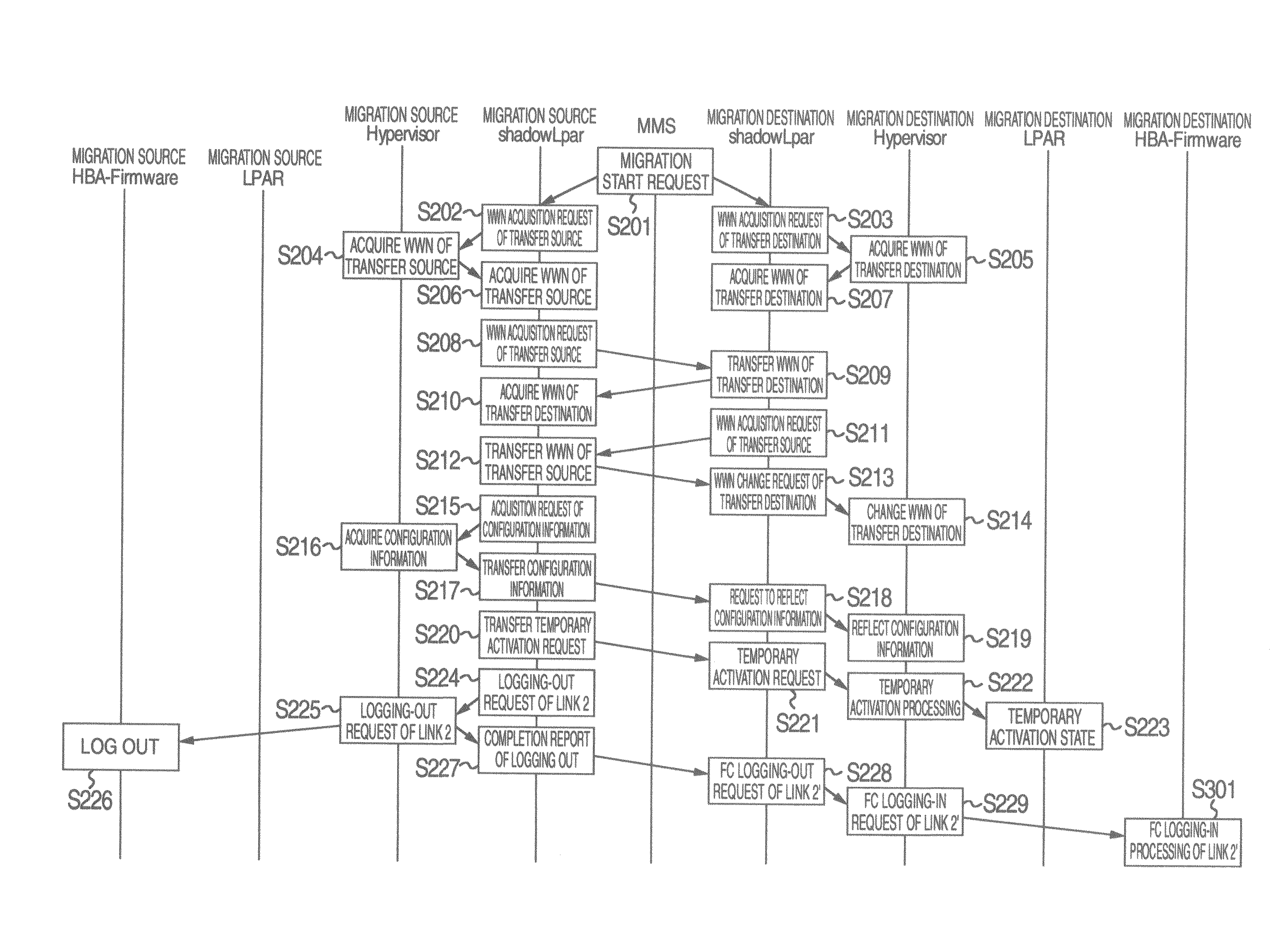
Enables immediate and uninterrupted access to disks at the migration destination, ensuring continuity of operations without requiring manual intervention in SAN management software.

Problems solved by technology

Accordingly, OS judges that logging-in processing is completed and makes disk access, although the logging-in processing is not performed actually and accordingly there arises a problem that disk access cannot be made after migration.

Method used


Image

  • Virtual computer system and migration method of virtual computer
  • Virtual computer system and migration method of virtual computer
  • Virtual computer system and migration method of virtual computer

Examples


embodiment 1

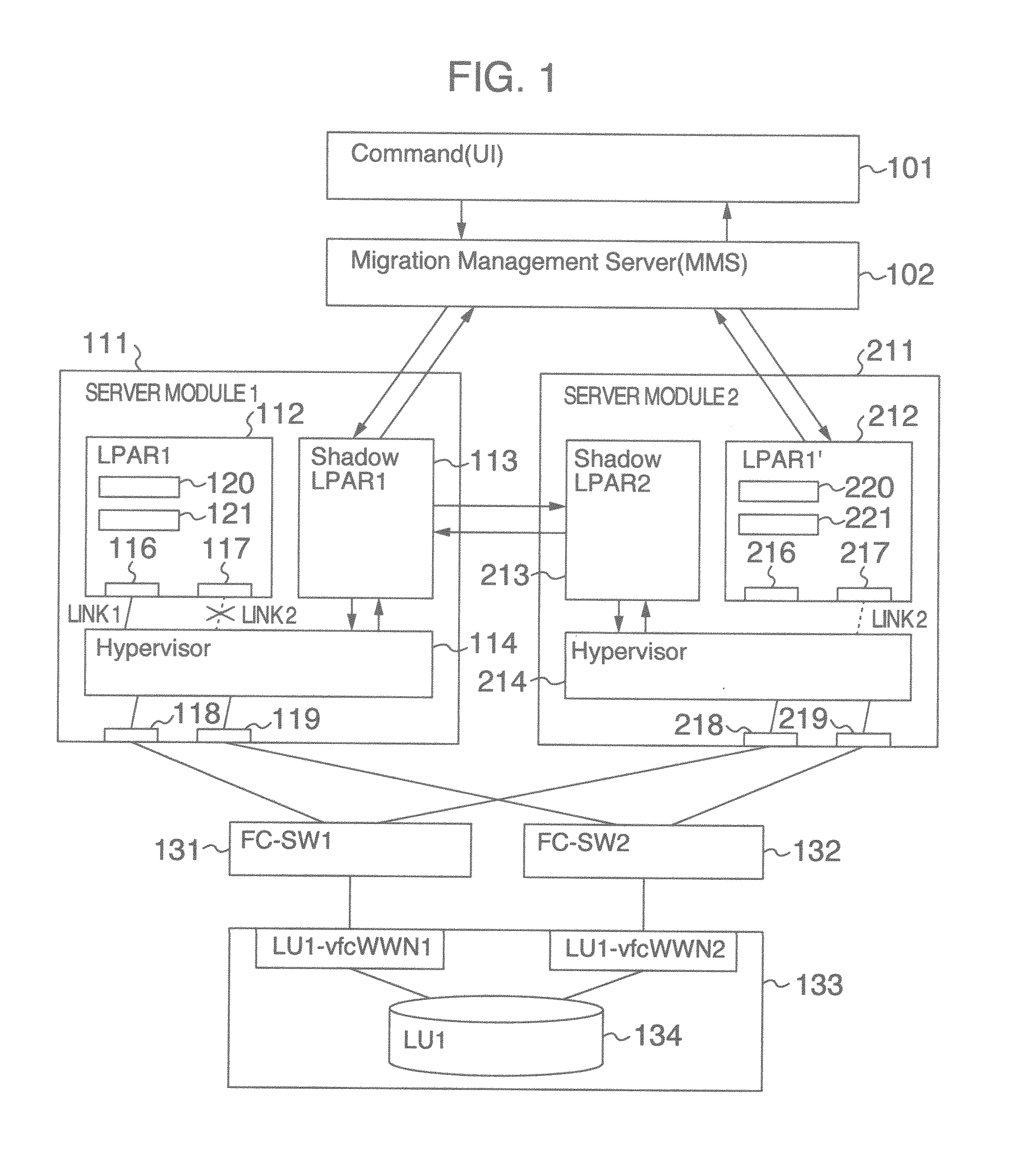
[0030]Referring now to FIG. 1, configuration of a virtual computer system of the embodiment 1 is described.

[0031]Servo-modules 111 and 211 have basically the same configuration and redundantly include FC-HBAs 118, 119 (218, 219) and NICs. Hypervisor 114 (214) is virtualization mechanism which makes one physical server look like a plurality of logical servers. Servo-modules 111 and 112 include LPAR 112 (212) and shadow LPAR 113 (213) which are constructed in one hypervisor to be operated. Shadow LPAR is LPAR exclusive to hypervisor and invisible to users and hypervisor can indirectly take in the function provided in shadow LPAR through LPAR.

[0032]FC-HBAs 118, 119 (218, 219) each have one WWN to one FC port as HBA address in order to make communication. LPAR 112 (212) also has two logical HBAs 116, 117 (216, 217) which are given inherent WWNs such as VfcWWN1, VfcWWN2 (VfcWWN3, VfcWWN4), respectively.

[0033]Storage or memory device 133 includes a disk unit 134 named LU (logical unit) lo...


PUM


Abstract

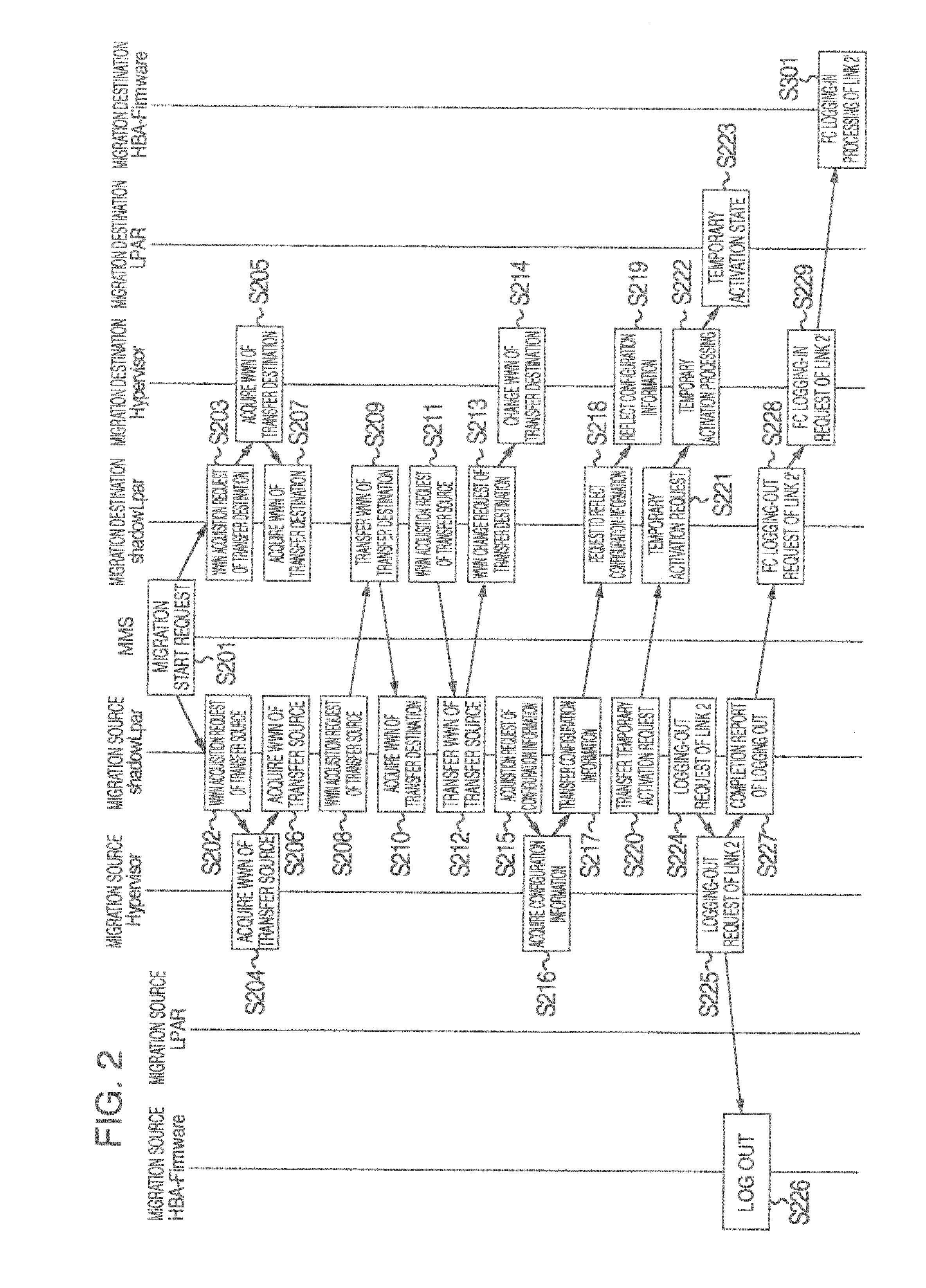
When LPAR in a physical computer is migrated to LPAR in another in the state that OS operates, OS in LPAR can access disk which the OS has accessed before migration just after migration. FC-HBAs connected to the physical computers of the source and destination are constructed redundantly and one FC port is set to logging-out state in migration source before resumption of OS on the way of migration. After logging-in processing of FC is performed beforehand in migration destination by means of WWN of FC logged out in migration source, processing is performed so that path between FC logged and disk is viewed as being on-line from only OS. Path between FC not logged at destination and disk is processed to be viewed as being off-line from OS just after OS operates at destination, so that OS at destination can access the disk.

Description

INCORPORATION BY REFERENCE[0001]The present application claims priority from Japanese application JP2010-258482 filed on Nov. 19, 2010, the content of which is hereby incorporated by reference into this application.BACKGROUND OF THE INVENTION[0002]The present invention relates to a method of migrating a logical partition being operated in a physical computer to a logical partition in another physical computer and its virtual computer system.[0003]A virtual computer system in which a plurality of logical computers or logical partitions (hereinafter abbreviated as LPAR) are constructed in a single physical computer and a plurality of inherent operating systems (OSs) can be operated in the plurality of logical computers is put to practical use. Furthermore, recently, there is also an example in which a virtual computer system in which logical FC (fibre channel) expansion boards or FC ports are provided in respective logical computers is used in SAN (storage area network) environment co...

Claims


Application Information

Patent Timeline
Patent Type & Authority Patents(United States)
IPC IPC(8): G06F9/455
CPCG06F9/5077
Inventor HATTA, YUKARIOIWA, EIICHIRO
Owner HITACHI LTD
Learn More