Climate control duct architecture for a vehicle

a technology of duct system and climate control, which is applied in the direction of ventilation system, heating type, lighting and heating apparatus, etc., can solve the problems of low console airflow of known systems, continuous challenges to climate control designers, and compromise of the necessary duct package, etc., to achieve the effect of reducing air turbulence, increasing airflow through the duct system, and reducing energy requirements

Active Publication Date: 2013-12-17
FORD GLOBAL TECH LLC
View PDF64 Cites 11 Cited by
  • Summary
  • Abstract
  • Description
  • Claims
  • Application Information

AI Technical Summary

Benefits of technology

[0009]By providing for the distribution of air at the exit of the HVAC the arrangement disclosed herein reduces air turbulence thus increasing airflow through the duct system. This streamlined arrangement virtually eliminates disorganized airflow and the consequential deceleration and acceleration by splitting airflow directed to each outlet at the earliest stage of the airflow path. The arrangement of the present invention provides optimum airflow with minimum energy requirements.

Problems solved by technology

Accordingly, the package needed for ducts often gets compromised.
This, together with the new designs of instrument panels that often have more lay back angles, brings about continuous challenges to climate control designers to engineer systems that deliver acceptable levels of vehicle airflow.
As a consequence, console airflow of known systems often ends up being low and the comfort levels of the rear passengers are often not attained.

Method used


Image

  • Climate control duct architecture for a vehicle
  • Climate control duct architecture for a vehicle
  • Climate control duct architecture for a vehicle

Examples


Embodiment Construction

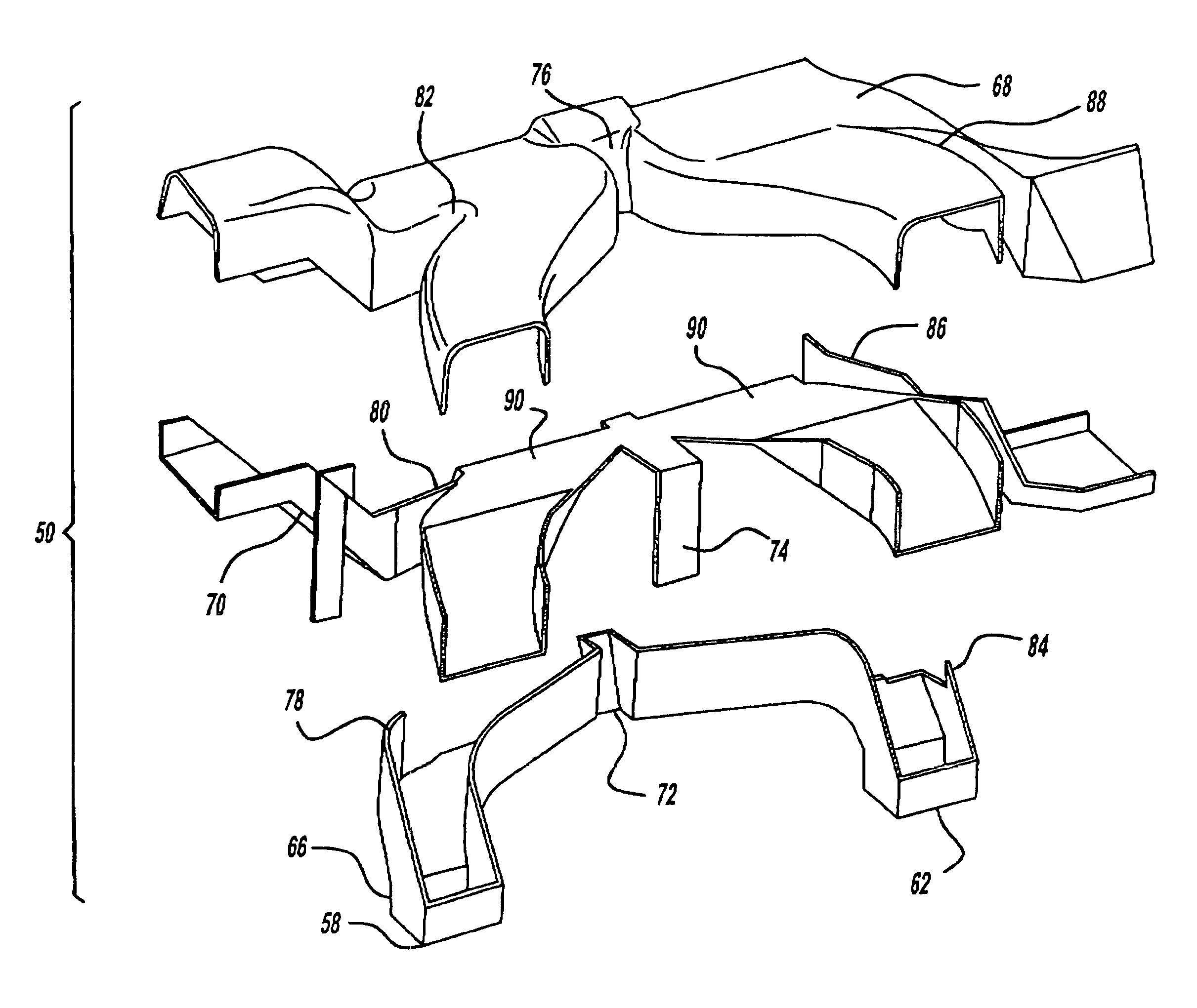
[0021]In the following figures, the same reference numerals are used to refer to the same components. In the following description, various operating parameters and components are described for one constructed embodiment. These specific parameters and components are included as examples and are not meant to be limiting.

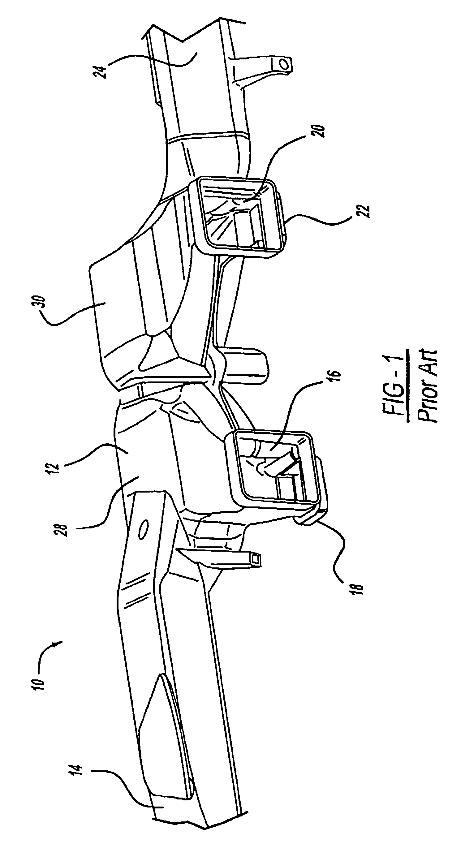
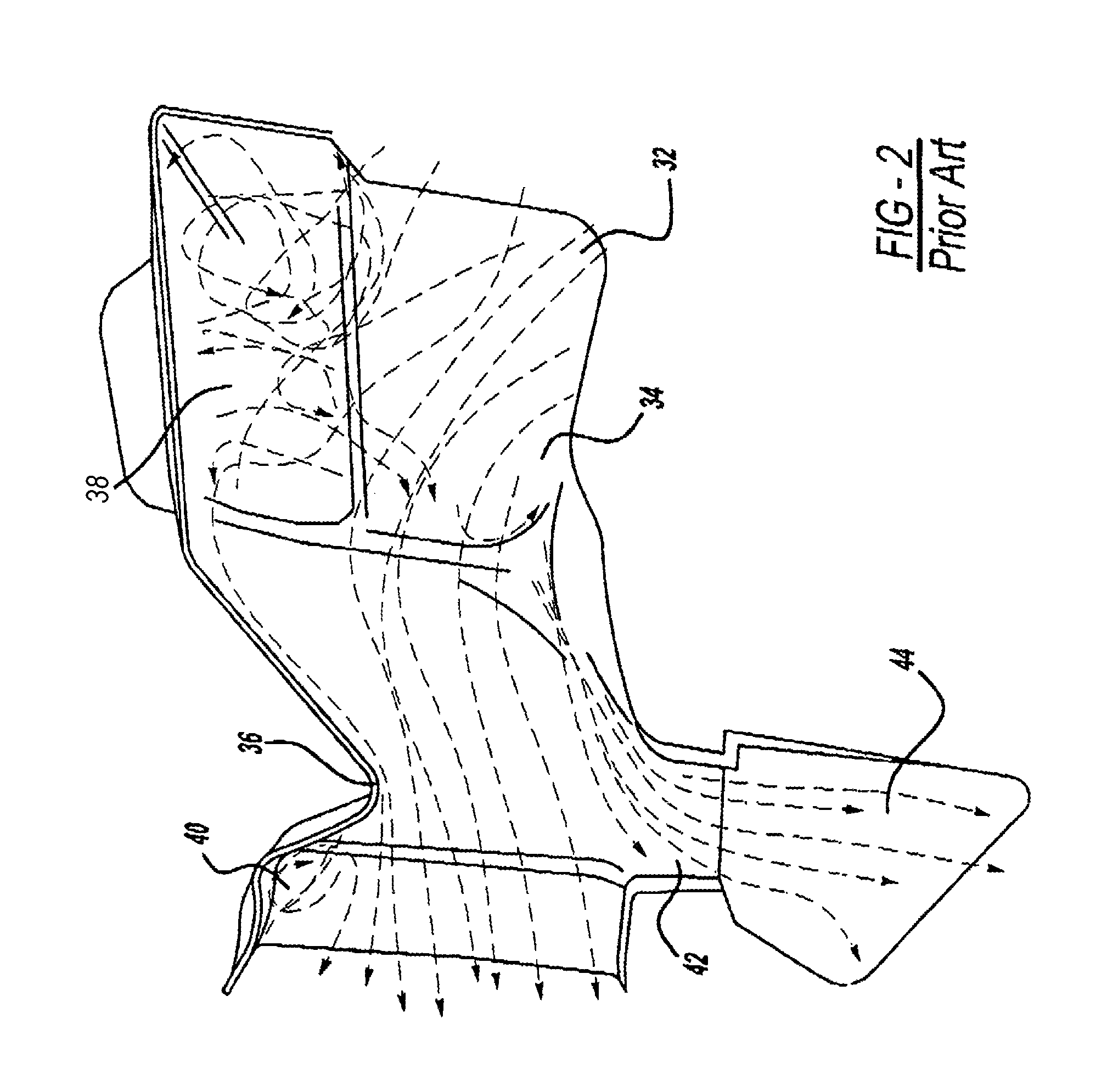
[0022]With reference to FIG. 1, a perspective view of an airflow distribution duct according to the known art, generally illustrated as 10, is shown. The airflow distribution duct 10 includes a body 12, a first outlet 14, a second outlet 16, a third outlet 18, a fourth outlet 20, a fifth outlet 22, and a sixth outlet 24. There can be a greater or lesser number of outlets as is known in the art and the arrangement shown is only for illustrative purposes as representing the state of the prior art. Of particular interest is the body 12 which conventionally includes a plenum section for receiving inflowing air coming from the HVAC to which individual outlets 14, 16, 18, 2...


PUM


Abstract

A climate control duct architecture having partitions to provide effective distribution of air immediately as it exits the HVAC. By strategic positioning and configuring of the partitions the duct architecture may be tuned to provide maximum console airflow and desired system airflow distribution with a minimum amount of interference to the airflow due to turbulence.

Description

TECHNICAL FIELD[0001]The present invention relates generally to climate control duct systems for vehicles. More particularly, the present invention relates to a climate control duct architecture that includes partitions which provide distribution of air as it exits the HVAC. By strategic positioning and configuring of the partitions the duct architecture may be tuned to provide maximum console airflow and desired distribution across the system with a minimum amount of interference to the airflow due to turbulence.BACKGROUND OF THE INVENTION[0002]Modern vehicle interiors are provided with climate control systems. Central to the climate control system is the HVAC which produces climatized air for distribution into the interior of the vehicle through a variety of ducts. Known arrangements of ducts in climate control systems include a path to the panel registers and to the console which takes place at a distance away from the air outlet of the HVAC. Essentially such systems build a plen...

Claims


Application Information

Patent Timeline
Patent Type & Authority Patents(United States)
IPC IPC(8): B60H1/24F24F7/04
CPCB60H1/00564B60H2001/00092B60H1/242B60H1/246
Inventor KUMAR, MUKESHHOKE, PAULDOROUDIAN, MARK
Owner FORD GLOBAL TECH LLC
Why Eureka
Try Eureka