Block matching method

a matching method and block technology, applied in image analysis, instruments, computing, etc., can solve the problems of inability to correctly determine the actual moving direction of objects in the image, and the resultant motion vector is often prone to errors, so as to correctly estimate the motion vector and filter out interference from different objects

Inactive Publication Date: 2013-12-17
NOVATEK MICROELECTRONICS CORP
View PDF4 Cites 3 Cited by
  • Summary
  • Abstract
  • Description
  • Claims
  • Application Information

AI Technical Summary

Benefits of technology

[0006]Therefore, a primary objective of the present invention is to provide a block matching method capable of correctly estimating a motion vector through using a mask area to filter out interference from different objects.

Problems solved by technology

In such a case, a resultant motion vector is often prone to errors, due to a mixed presence of different (or greatly varying) object motions within the same block.
Therefore, an actual moving direction of the objects in the image cannot be correctly determined.

Method used


Image

  • Block matching method
  • Block matching method
  • Block matching method

Examples


Embodiment Construction

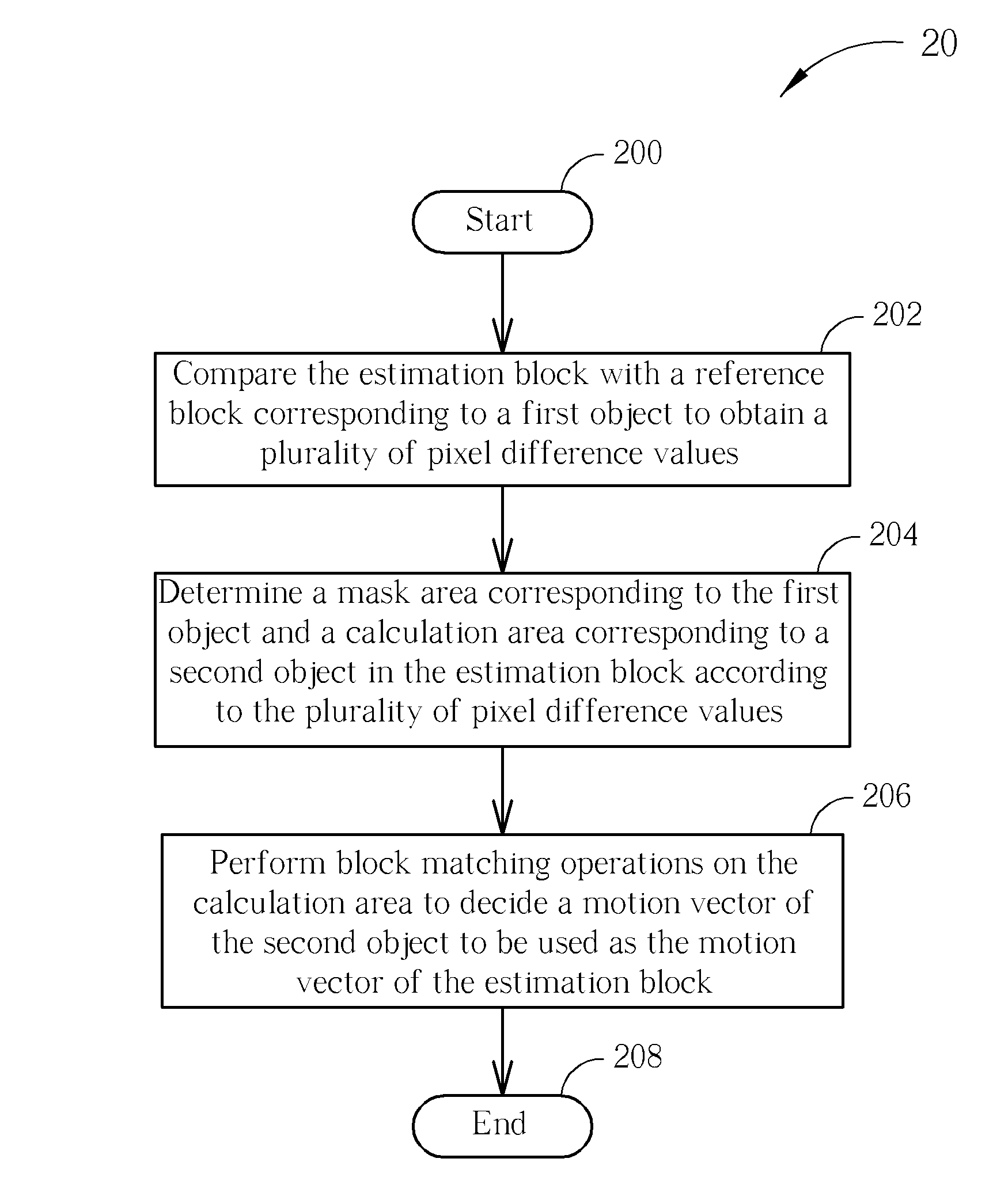
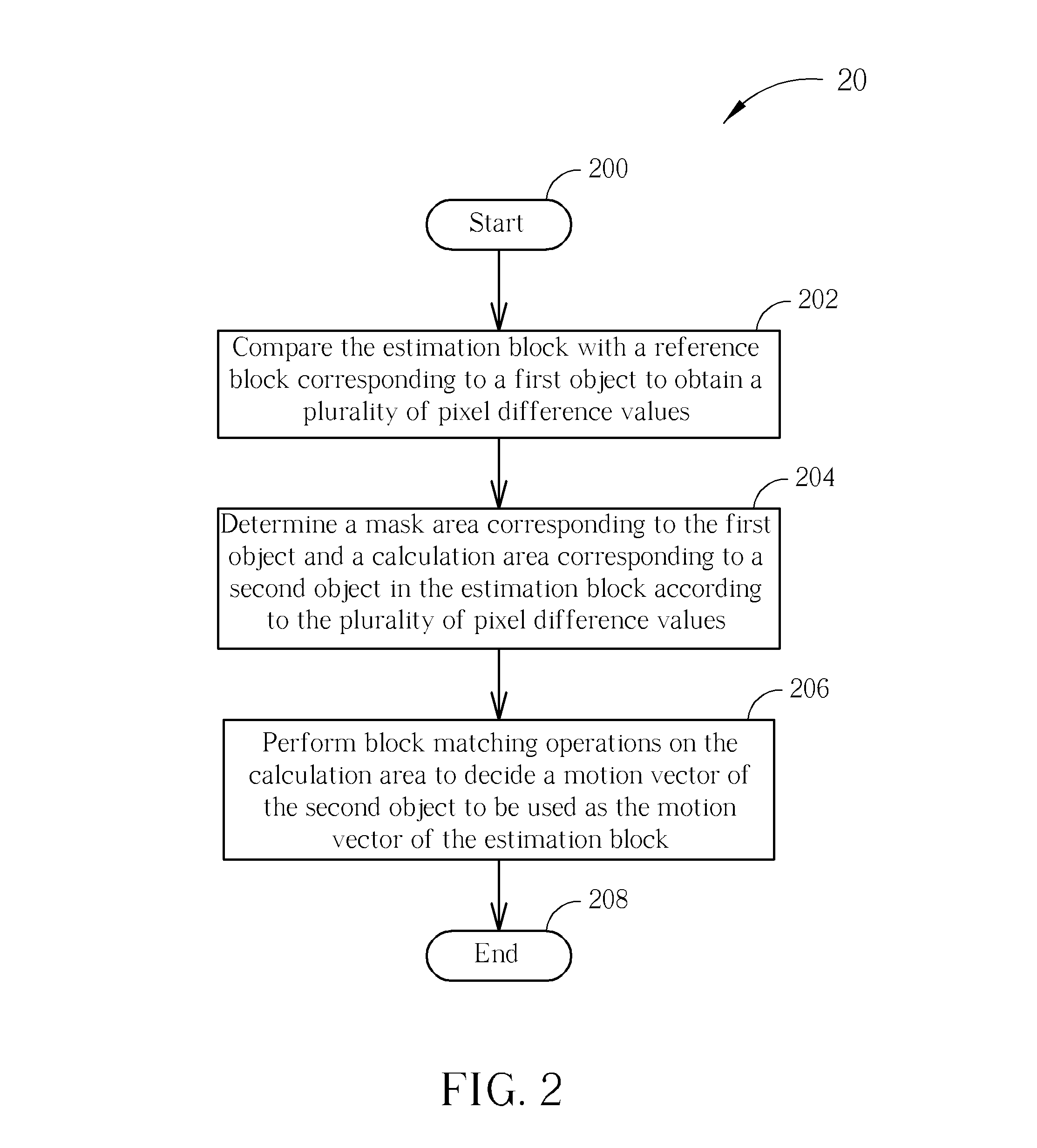
[0013]Please refer to FIG. 2, which is a schematic diagram of a block matching process 20 according to an embodiment. The block matching process 20 is used for estimating a motion vector of an estimation block of an image frame. The process 20 includes the following steps:

[0014]Step 200: Start.

[0015]Step 202: Compare the estimation block with a reference block corresponding to a first object to obtain a plurality of pixel difference values.

[0016]Step 204: Determine a mask area corresponding to the first object and a calculation area corresponding to a second object in the estimation block according to the plurality of pixel difference values.

[0017]Step 206: Perform block matching operations on the calculation area to decide a motion vector of the second object to be used as the motion vector of the estimation block.

[0018]Step 208: End.

[0019]According to the process 20, motion estimation attempts to determine a motion vector required for a decoding process during an image encoding pr...


PUM


Abstract

A block matching method for estimating a motion vector of an estimation block of an image frame is provided, which includes comparing the estimation block with at least one reference block corresponding to a first object to obtain a plurality of pixel difference values, determining a mask area corresponding to the first object and a calculation area corresponding to a second object in the estimation block, and performing blocking matching operations on the calculation area to determine a motion vector of the second object as the motion vector of the estimation block.

Description

BACKGROUND OF THE INVENTION[0001]1. Field of the Invention[0002]The invention relates to a block matching method, and more particularly, to a block matching method capable of correctly determining a motion vector by utilizing a mask area to filter out interference from other objects.[0003]2. Description of the Prior Art[0004]Motion estimation is an important technique used in video compression, its objective being to reduce redundant information from video frames at various time points. Generally, a video achieves an illusion of motion through playback of a series of still images differentiated by subtle variations between two consecutive frames, as a result of persistence of human vision. Moreover, images in two adjacent frames are usually almost identical, distinguished by only slight or even no variation. In such a case, it is unnecessary to store unchanging parts of an image, and only necessary to make slight modifications to previous images. In short, during video encoding / deco...

Claims


Application Information

Patent Timeline
Patent Type & Authority Patents(United States)
IPC IPC(8): G06K9/00
CPCG06T7/2013G06T7/223
Inventor CHEN, TSUI-CHINLIU, YU-SHUHSIEH, WAN-HSIHU, YU-TSUNG
Owner NOVATEK MICROELECTRONICS CORP
Why Eureka
Try Eureka