Device for generating analog current or voltage signal

a technology of current generator and analog current, applied in the direction of electric controller, program control, instruments, etc., can solve the problems of insufficient current generator command, inconvenient operation, and inability to meet the requirements of the current generator, so as to reduce the structural problems

Inactive Publication Date: 2011-03-22
ABB OY
View PDF6 Cites 1 Cited by
  • Summary
  • Abstract
  • Description
  • Claims
  • Application Information

AI Technical Summary

Benefits of technology

[0005]According to the invention, absolute values of output variables are measured and regulated continuously to ensure the correctness of the signal. According to an embodiment, the actual current or voltage value of an analog output signal is measured and digitized, the difference between said digitized actual current or voltage value and a desired current or voltage value is determined, and the generation of the analog output signal is controlled with a digital control signal in such a manner that said difference decreases. With the solution of the invention, the absolute accuracy and stability of the analog output signal only depend on the accuracy of the measurement and digitizing. All errors of the circuit branch generating the analog signal are compensated through a feedback loop, because if the output signal does not correspond to the command value, the generation of the analog output signal is immediately controlled with a digital control signal to decrease said difference. With the invention, conversion from digital control to an analog output signal can be achieved using an inexpensive solution, because the accuracy of the conversion need not be set as strict requirements as before. Even though the invention requires measuring and digitizing the output signal, the device is still as a whole inexpensive, because an accurate A / D converter is considerably less expensive than an accurate D / A converter whose accuracy and stability is further reduced by the separate buffering required in the output. According to an embodiment of the invention, the digitizing of the measurement is performed with a sigma-delta (Σ / Δ) modulator. A sigma-delta modulator is, due to its mode of operation, particularly resistant to different interference peaks, and its absolute accuracy and stability are excellent. In an embodiment of the invention, a digitized 1-bit signal generated by a sigma-delta modulator is digitally filtered and decimated to obtain a multibit, digitized, actual current or voltage value.
[0006]In various embodiments of the invention, there is preferably galvanic separation between the analog output and digital control. This reduces interference and errors that propagate to points critical to the accuracy of the device. Galvanic separation also provides a safety feature in case a signal in network potential, for instance, was connected by accident the analog output connectors. In an embodiment of the invention, digitizing is performed using an analog-to-digital conversion circuit, such as a sigma-delta modulator with integrated galvanic separation between the input and output. Correspondingly, a digital-to-analog conversion circuit with integrated galvanic separation between the input and output may be used in digital-to-analog conversion. Alternatively, it is possible to use separate galvanically separating circuits. In an embodiment of the invention, galvanic separation is implemented with an integrated DC-to-DC converter. It is further possible to use in the circuit branch (D / A) generating the voltage and the digitizing measuring branch (A / D) galvanic separation methods that differ from each other. In various embodiments of the invention, the power source of the analog parts of the device may be galvanically separated from other operating voltages of the surrounding equipment, such as an electric motor drive.
[0008]The device of the invention is intended primarily for use in measuring and control signal transmitters. A particular field of application is electric motor drives. In an electric motor drive comprising a device of the invention, a circuit branch generating an analog output and a digitizing measuring branch are provided on a separate circuit board that is mounted in a circuit board connector on a main circuit board of the motor drive, and the control means that receive a digitized measuring signal and generate a digital control signal are provided on the main circuit board. With these solutions, it is possible to reduce the structural problems associated with traditional measuring and control signal transmitters.

Problems solved by technology

Conventionally used current loops have several drawbacks that in certain cases may even lead to dangerous situations.
If high accuracy or resolution is required of the current loop, a current generator command formed by the PWM technique is usually not sufficient and a D / A converter with the required accuracy and resolution can be used.
In both cases, current calibration and stability are completely dependent on fixed components, whereby the temperature dependency of the components may cause unexpected errors.
Thus, there is no certainty as to the actual amount of the current passing through the current loop and whether the current loop has possibly been broken, in which case the analog gauge it controls will misleadingly indicate a zero value, even though the connection may in reality be dangerous because it is live.
Conventional current transmitters are not able to do this.
If high accuracy or resolution is required of the current loop, a current generator command formed by a PWM technique is usually not sufficient and a D / A converter with the required accuracy and resolution needs to be used.
The temperature dependency of the actual current generator part may still bring about unexpected errors that cannot be detected at all.
In addition, accurate or high-resolution D / A converters are expensive which increases the costs of the signal transmitter.

Method used


Image

  • Device for generating analog current or voltage signal
  • Device for generating analog current or voltage signal

Examples


Embodiment Construction

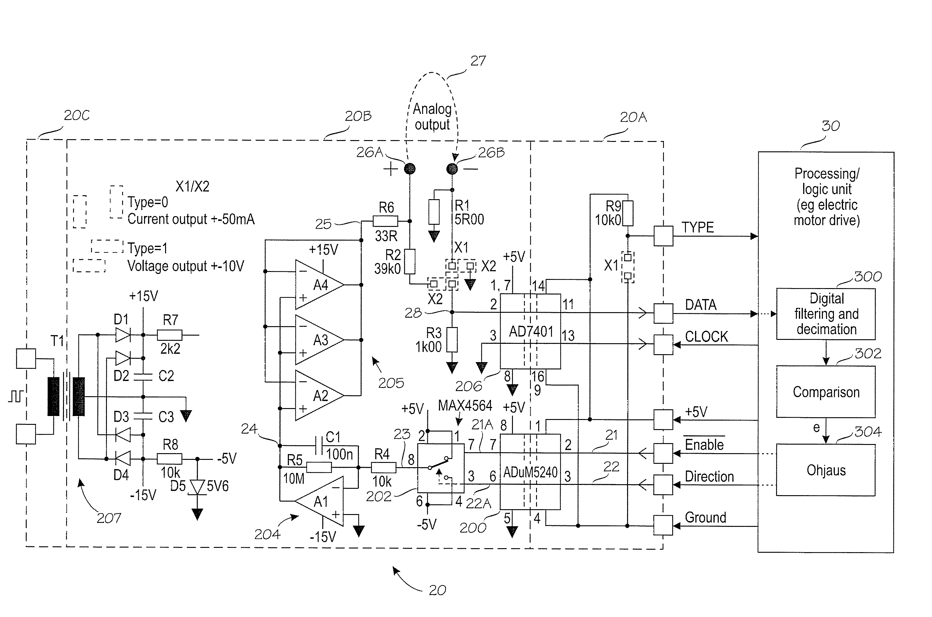
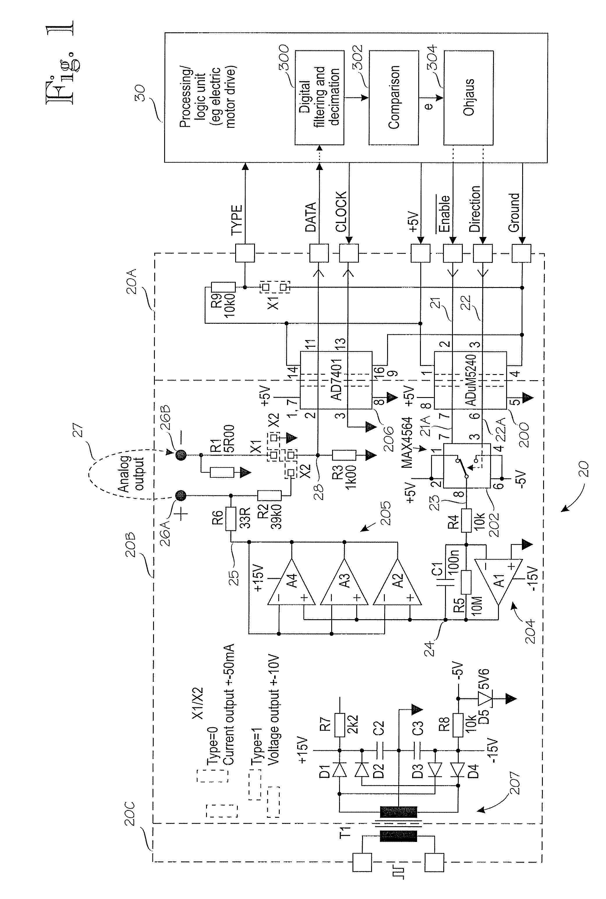
[0010]In the example shown in FIG. 1, the invention is implemented with two separate modules (e.g. circuit boards) 20 and 30, but it may also be implemented as one or more modules.

[0011]Control module 20 generates an analog current or voltage output in accordance with digital information Enable supplied by module 30, and generates to module 30 a digitized signal DATA that represents the actual current or voltage value measured from the analog output. In the example, output TYPE from module 20 indicates to module 30 whether the analog output is a current signal (e.g. 4 to 20 mA) or voltage output (e.g. 0 to 10 V). In the example, module 20 generating the analog outputs can be configured to be used as either a current or voltage output by transposing only two bridge or jumper links X1 and X2, but module 20 may also be implemented as a current or voltage output only. The specified ±50-mA current output range of module 20 is selected to suit all most conventional current loop types and ...


PUM


Abstract

In a device, such as measuring or control signal transmitter, generating an analog current or voltage output signal, absolute values of output variables are continuously measured and regulated to ensure the correctness of the signal. The actual current or voltage value of an analog output signal is measured and digitized (206), a difference (e) between the digitized actual current or voltage value and the desired current or voltage value is defined (300), and the generation (200, 202, 204, 205) of the analog output signal is controlled (304) by means of a digital control signal (Enable, Direction) so as to decrease the difference.

Description

BACKGROUND OF THE INVENTION[0001]The invention relates to electronic devices for generating a current and voltage signal.[0002]In industrial instrumentation, electric drives, such as motor drives and frequency converters, and other drives, analog outputs are often needed to signal various matters related to the operation of the drive. These include control and regulating signals or measuring signals. A 4 to 20-mA current loop is one analog electric communication standard that is generally used in this type of analog signaling. In a 4 to 20-mA current loop a 4-mA loop current typically represents a 0% signal value and 20 mA represents a 100% signal value. Correspondingly, a voltage signal, such as a 0 to 10-VDC voltage signal, can be used in analog signaling. In instrumentation, a device generating and transmitting an analog signal is generally called as a transmitter. Current loops in particular are often used to control separate analog panel gauges due to their easy readability.[00...

Claims


Application Information

Patent Timeline
Patent Type & Authority Patents(United States)
IPC IPC(8): G05B19/29
CPCG08C19/02H03L5/00
Inventor MIETTINEN, ERKKI
Owner ABB OY
Why Eureka
Try Eureka