[0008]One objective of the present invention is to provide a multi-antenna integration module, which uses a structure having a common conductor, a common short-circuit member and a common ground member as the common radiator of several antenna systems, whereby the module of the present invention not only occupies much less space but also is easy-to-
layout and easy-to-assemble for various electronic devices.
[0009]Another objective of the present invention is to provide a multi-antenna integration module, wherein the design of a common unit is used to integrate several antenna structures into a single structure, whereby the interference among different antennae is reduced, and whereby the isolation and the radiation
gain are increased.
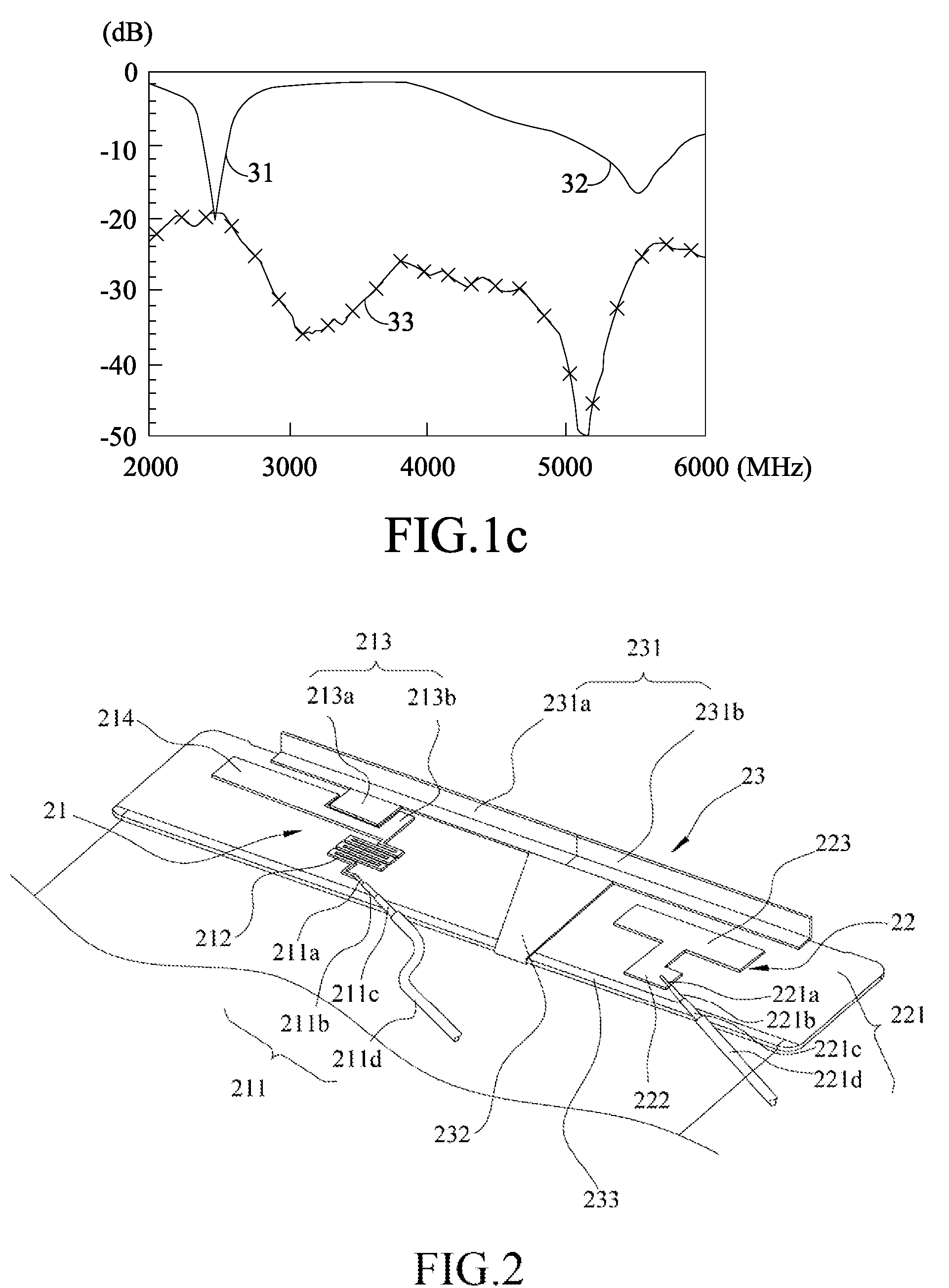
[0011]In the first antenna of a first embodiment of the present invention, a feed-in
signal is input from the first feeder cable and coupled to the first conductor of the common conductor by the feeder member and the coupling unit. The common conductor receives the electrically coupled
signal of the first antenna and transmits it to the common short-circuit member and the common ground member. Thus, the coupling unit, the extension conductor and the common unit cooperate to form the main radiation structure of the first antenna, wherein the common conductor and the extension conductor are respectively used to excite a low-frequency resonant mode and a high-frequency resonant mode of the first antenna. The feeder member and the coupling unit respectively have an inductive
reactance and a capacitive
reactance. The feeder member and the coupling unit jointly form a resonant structure to realize two functions: regulating the
input impedance of the first antenna to make the excitation mode thereof have a superior
impedance matching; and appropriately modulating the resonant
reactance to create a filtering effect and effectively isolate the signal of the second antenna from the first antenna, whereby the first antenna can be exempted from the
signal interference of the second antenna, and the
isolation effect between the two antennae is promoted.
[0012]In the second antenna of this embodiment, a feed-in signal is input from the second feeder cable and coupled to the second conductor of the common conductor by the radiation conductor and the coupling conductor. The common conductor receives the electrically coupled signal of the second antenna and transmits it to the common short-circuit member and the common ground member. Thus, the radiation conductor, the coupling conductor and the common unit cooperate to form the main radiation structure of the second antenna, wherein the common conductor is used to excite a resonant mode of the second antenna. Via an appropriate design, the radiation conductor has an inductive reactance; the coupling conductor together with the second conductor has a capacitive reactance. The radiation conductor, the coupling conductor and the second conductor jointly form a resonant structure having two functions: regulating the
input impedance of the second antenna to make the excitation mode thereof have a superior
impedance matching; and appropriately modulating the resonant reactance to create a filtering effect and effectively isolate the signal of the first antenna from the second antenna, whereby the second antenna can be exempted from the
signal interference of the first antenna, and the
isolation effect between the two antennae is promoted.
[0013]The present invention also has a second embodiment similar to the first embodiment except the second antenna additionally has a matching member. One end of the matching member is connected to one side of the radiation conductor, and another end of the matching member is connected to the common ground member. The matching member is used to modulate the
impedance matching of the second antenna so that the
system of the second antenna can have a better operation bandwidth. In the second embodiment, the extension portion of the radiation conductor, which is connected to the coupling conductor, is fabricated into a serpentine shape to increase the inductive reactance of the second antenna, whereby the filtering effect of the second antenna is increased, and the isolation effect between two antennae is promoted.
[0014]In the present invention, the design of the common unit integrates the radiation conductors, short-circuit members and ground members of different antenna systems into a single structure, whereby different antenna systems can share a common radiator. Via the design of feeding signal into the resonant structure, the present invention is exempted from mutual signal interferences of different antennae, and the
gain of
antenna radiation is free of the influence of signal interferences. Via integrating several sets of antennae into a single structure, the present invention can solve the conventional problem that an electronic device has to be embedded with several sets of antennae and thus can reduce the space occupied by the antenna
layout. Therefore, the multi-antenna integration module of the present invention is easy-to-layout and easy-to-assemble for various electronic devices.


