Window structure with expansion member for inhibiting flood waters

a technology of expansion member and window structure, which is applied in the direction of door/window protective device, frame fastening, rain/draught deflector, etc., can solve the problem of not being able to predict how much water a flooding event will produce, and the area being susceptible to flooding may chang

Active Publication Date: 2013-12-24
DEERHILL PROPERTIES
View PDF34 Cites 10 Cited by
  • Summary
  • Abstract
  • Description
  • Claims
  • Application Information

AI Technical Summary

Benefits of technology

[0020]Expansion of the mechanical seal may occur upon a force being received within the open end of the mechanical seal and exerted on the tapered end of the mechanical seal. When the mechanical seal expands the mechanical seal wedges further between the window opening and the frame for inhibition of flood seepage. In addition, the use of an expansion member will force the mechanical seal into position. It is recognized that many years may pass before a flood condition occurs, and the mechanical seal may have taken on an aged set. The use of an expansion member will assure that the mechanical seal is tightly sealed to the structure to prevent water passage.
[0021]Accordingly, it is an objective of the present invention to provide a flood barrier system for first floor windows where the property owner need not have to perform regular maintenance or perform manual labor in preparation for a disaster to protect the building contents. Alternatively, the flood barrier system may be installed from the ground floor for building structures in coastal areas erected on stilts.
[0025]It is an objective of the present invention to provide a flood barrier system whereby the mechanical seal is memory shaped to expand when a force is introduced therethrough and return a substantially original position, and the use of an expansion member will create a seal when the expansion member is wetted.
[0027]It is an objective of the present invention to provide a glass flood barrier system that can be adapted to any building opening comprising of existing slabs and walls openings capable of supporting a flood before the flood barrier system is installed.

Problems solved by technology

Floods are common in areas that do not have adequate drainage to handle a high influx of water.
Unfortunately, whether an area is susceptible to flooding may change from year to year due to drainage changes as a result of construction, forest growth, river silting, and the like.
Unfortunately, it is not possible to predict how much water a flooding event will produce, for the flooding may be caused by upriver snowmelt or rain, locally heavy rainfall, high winds, and similar events that cause water stacking, a drainage malfunction, or the like any of which may cause flood waters to breech a building structure.
Flooding may not damage a building structure but it can be devastating on the contents within the building should water be allowed to enter the structure.
Most buildings are designed to keep out rain, but they are not necessarily designed to keep out flood water.
If the pressure is substantially high or the water level is high enough then loads of water will seep past the sandbags and flood the area.
The principle disadvantage of emergency measures is that sufficient advance warning is required to mobilize personnel and install emergency barriers.
Most emergency flood proofing methods require extensive labor force, depend on the availability of heavy machinery and trained operators on short notice, and necessitate a large amount of storage space.
Furthermore, if the magnitude or the rate of the rise of a flood is misjudged the emergency flood proofing techniques fail.
Not to mention aesthetically any emergency flood proofing measure is difficult to bear if left for long periods of time.
Another disadvantage is that emergency measures do not satisfy the minimum requirements for watertight flood proofing as set forth by the National Flood Insurance Program for the protection of an existing construction.
However, the operable jack is exposed to the elements and susceptible to corrosion; this device requires proper maintenance to insure integrity.
Unfortunately, these flood shield devices are expensive, proper storage is required, and tools are needed for proper installation.
Again, movable floodwall devices are expensive and require proper maintenance.
For example, the amount of pressure exerted on a window pane during a flood may be a load the window pane cannot handle.
The breached window pane provides a point of entry for wind or water whereby the water enters the building structure and causes severe damage to the infrastructure of the home, upholstery, and furniture and eventually causing sever molding.
Therefore, it takes the entire window system to make a seal proof opening within the window cavity.
The impact resistant window pane may provide protection from wind, missiles, debris, and water against the window pane but if the frame is not properly installed a load could hit the window pane and cause the entire frame to come off the retaining wall defining a window cavity.
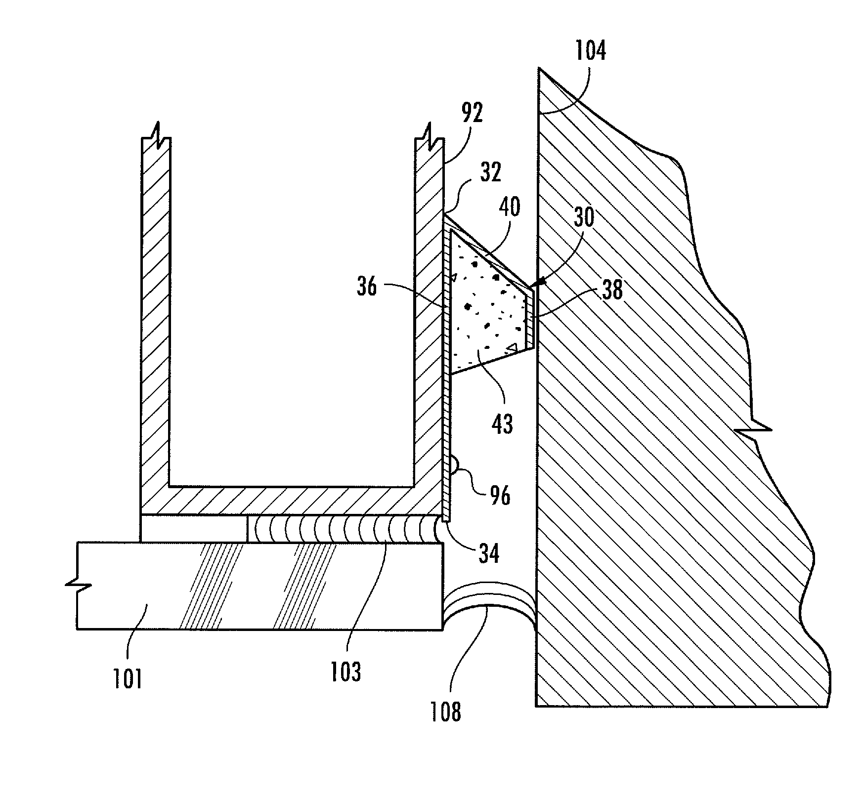
Aside from the window pane and frame being susceptible to being struck or blown in by flood water, the gap between the window frame and the retaining wall is especially vulnerable.
Water seeping into the building structure through the area between the frame and retaining wall in which it was installed presents a glaring problem.
Caulk has a limited life which is further shortened upon exposure to the elements such as UV light.
Caulk that has degraded may become a brittle and lack any ability to prevent water from entering the space between the frame and the structure.
Caulk that has minimal shrinkage may appear capable of preventing water passage, however, the shrinkage may create a latent condition wherein the failure occurs when a seal is most important.
Caulk is particularly susceptible to environmental temperature as it expands and contracts leaving potential openings within the gap.
During a flood, water pressure builds up on the window frame and if the caulking is brittle the water pressure may be such that it surges pass the caulking and enters the building structure.
While these prior art techniques may be suitable for the particular purpose to which they address, they do not present a method of inhibiting flood water entry into a structure about a window frame.

Method used


Image

  • Window structure with expansion member for inhibiting flood waters
  • Window structure with expansion member for inhibiting flood waters
  • Window structure with expansion member for inhibiting flood waters

Examples


Embodiment Construction

[0064]Detailed embodiments of the instant invention are disclosed herein, however, it is to be understood that the disclosed embodiments are merely exemplary of the invention, which may be embodied in various forms. Therefore, specific functional and structural details disclosed herein are not to be interpreted as limiting, but merely as a basis for the claims and as a representation basis for teaching one skilled in the art to variously employ the present invention in virtually any appropriately detailed structure.

[0065]Referring now to FIGS. 1-30, wherein like components are numbered consistently throughout, an improvement in window construction, herein known as a flood barrier system 1. The system 1 illustrated in FIGS. 1-2 comprises of a frame member 10 and a mechanical seal 30, the words used interchangeably in this application. The flood barrier system 1 is constructed to adapt into a cavity or window opening 11 in a building structure. The frame 10 includes a top wall 12, a b...


PUM


Abstract

A flood barrier system for windows for inhibiting a water breach into a residential or commercial structure. The flood barrier is adapted to fit within a retaining wall cavity using an expansion member to assist a mechanical seal so as to stop water intrusion. The barrier operates with an extruded frame having vertical reveal members and high strength glass. A sealing joint is fitted about the retaining wall and the flood barrier's vertical reveal members for inhibition of flood seepage. The sealing joint, having at least three surfaces forming an open end and a tapered end, is anchored at the bottom wall of the extruded frame member and about the glass flood barrier's vertical reveal members at least 12 inches above the base flood elevation level. Alternatively, a flood panel can be installed in front of the windows for additional protection against water intrusion into the residential or commercial structure.

Description

CROSS REFERENCE TO RELATED APPLICATIONS[0001]This application is a continuation-in-part, and claims the priority date, of U.S. patent application Ser. No. 12 / 577,577, entitled “Window Structure for Inhibiting Flood Waters”, filed Oct. 12, 2009 now abandoned. U.S. patent application Ser. No. 12 / 577,577 is a continuation-in-part, and claims the priority date, of U.S. patent application Ser. No. 12 / 256,899, entitled “Window Structure for Inhibiting Flood Waters”, filed Oct. 23, 2008 now abandoned, the contents of both applications are incorporated herein by reference.FIELD OF THE INVENTION[0002]This invention relates generally to flood barriers and, more particularly, to an improvement in window construction that inhibits flood waters from entering a structure by mechanically sealing a properly constructed and engineered window frame to a retaining wall.BACKGROUND OF THE INVENTION[0003]Floods are common in areas that do not have adequate drainage to handle a high influx of water. Unfor...

Claims


Application Information

Patent Timeline
Patent Type & Authority Patents(United States)
IPC IPC(8): E06B1/60E06B7/098E06B7/26E06B1/34E06B1/62
CPCE06B1/62E06B9/00E06B1/34E06B2001/626E06B2001/628E06B2009/007
Inventor DUDASH, BARBARA
Owner DEERHILL PROPERTIES
Why Eureka
Try Eureka