Air coupled acoustic aperiodic flat lens

Active Publication Date: 2013-12-31
GOVERNMENT OF THE UNITED STATES AS REPRESENTED BY THE SEC OF THE AIR FORCE
View PDF9 Cites 12 Cited by
  • Summary
  • Abstract
  • Description
  • Claims
  • Application Information

AI Technical Summary

Problems solved by technology

Although these structures have been demonstrated to have better resolution, they operated only in a narrow frequency range and had serious practical limitations.
Although the lens h

Method used


Image

  • Air coupled acoustic aperiodic flat lens
  • Air coupled acoustic aperiodic flat lens
  • Air coupled acoustic aperiodic flat lens

Examples


Embodiment Construction

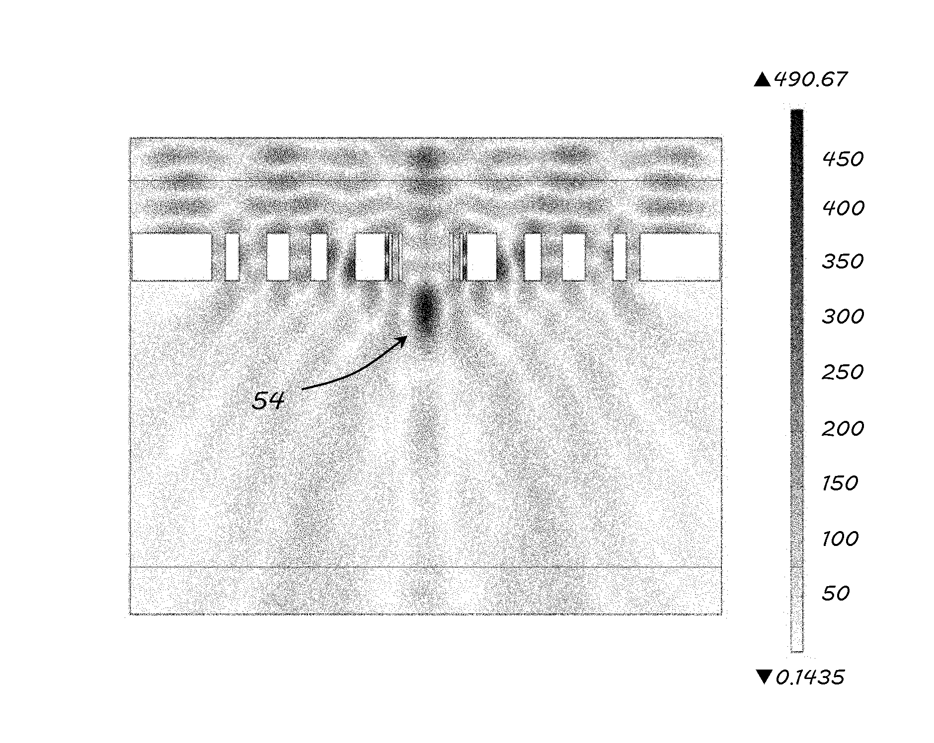
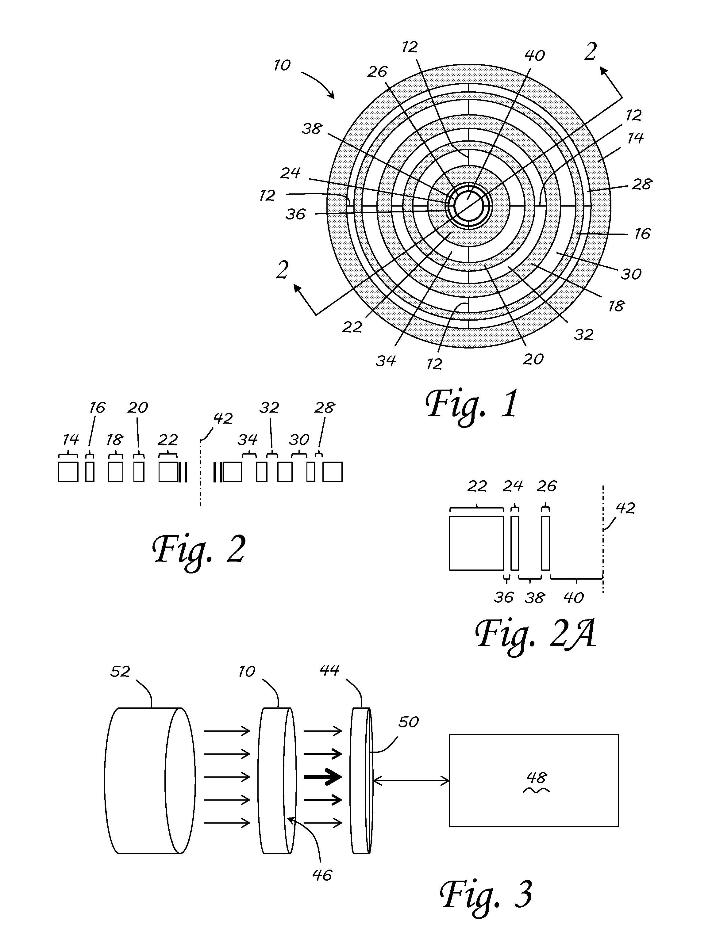
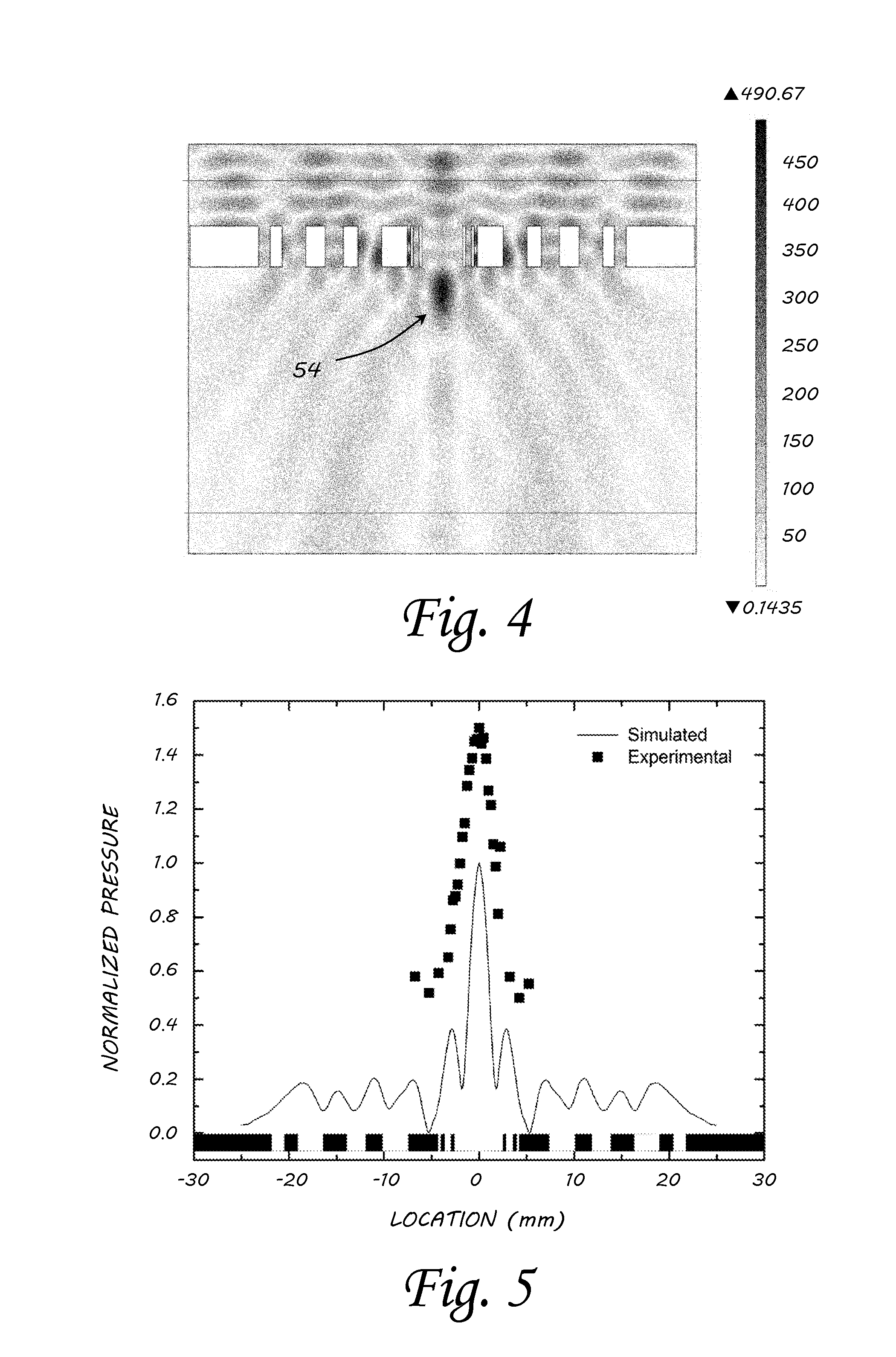
[0029]Embodiments of the invention provide sub-wavelength focusing with a flat lens. The general structure of the lens, as seen in FIG. 1, is a concentric ring structure with aperiodic ring width and spacing (gaps). The exemplary acoustic lens 10, includes four webs 12 to connect the rings 14, 16, 18, 20, 22, 24, 26 together at the rings' quadrants. The four webs 12 provide only support of the rings 14, 16, 18, 20, 22, 24, 26 in order to maintain proper spacing. While four webs were used in this exemplary embedment, any number of webs may be used to support the ring structure, though care should be taken to ensure that the web structure does not introduce significant interference in the lens structure.

[0030]The structure for the exemplary lens 10 is machined out of a solid piece of aluminum using an electrical discharge machining process. It is envisioned that this lens 10 could be made out of other materials as well, such as plastics, rubbers, or other metals, and that the lens 10 ...


PUM


Abstract

A broadband acoustic lens and method of designing same is provided for focusing an incident acoustic wave. The broadband lens includes a plurality of concentric rings, where each concentric ring of the plurality of concentric rings has a ring width, and a plurality of gaps, where each gap of the plurality of gaps has a spacing. The concentric rings are separated by a spacing corresponding to a gap of the plurality of gaps. The widths of the plurality of concentric rings and the spacings of the plurality of gaps are arranged such that the incident acoustic wave is focused to a spot within a sub-wavelength of the incident acoustic wave in air. The arrangement of the widths of the plurality of concentric rings and spacings of the plurality of gaps is aperiodic.

Description

RIGHTS OF THE GOVERNMENT[0001]The invention described herein may be manufactured and used by or for the Government of the United States for all governmental purposes without the payment of any royalty.BACKGROUND OF THE INVENTION[0002]1. Field of the Invention[0003]The present invention generally relates to focusing acoustic waves and, more particularly, to focusing utilizing acoustic lenses.[0004]2. Description of the Related Art[0005]Concepts of a “superlens” and its development have expanded the understanding of wave propagation and imaging across all fields of science and engineering. It is well known, from the theory of diffraction, that focusing of waves is limited by diffraction and the spatial resolution is determined by the Rayleigh criterion. The concept of the superlens has provided an avenue to obtain resolution beyond the classical diffraction limit. In general, in electromagnetic waves, the superlensing effect originates from a negative μ and negative ε, leading to nega...

Claims


Application Information

Patent Timeline
IPC IPC(8): G10K13/00
CPCG10K11/30G10K13/00
Inventor WELTER, JOHN TSATHISH, SHAMACHARYCHRISTENSEN, DANIELHEEBL, JASON DBRODRICK, PHILIPCHERRY, MATTHEW R
Owner GOVERNMENT OF THE UNITED STATES AS REPRESENTED BY THE SEC OF THE AIR FORCE
Why Eureka
Try Eureka