A capacitive coupling device and a filter

A capacitive coupling and air coupling technology, applied in the field of communication, can solve problems such as unfavorable dielectric filter design, and achieve the effects of small deformation, improved performance, and increased square coefficient.

Pending Publication Date: 2019-01-18
WUHAN FINGU ELECTRONICS TECH
View PDF11 Cites 13 Cited by
  • Summary
  • Abstract
  • Description
  • Claims
  • Application Information

AI Technical Summary

Problems solved by technology

For schemes 1 and 2, each time a capacitive cross-coupling is realized, an additional chamber space needs to be occupied in the horizontal direction; for scheme 3, in order to reverse the polarity, it is necessary to add a screw sleeve or a cover plate, also It is necessary to increase the height space in the vertical direction, which is not conducive to the design of the dielectric filter with relatively strict space, so the existing technology needs to be improved

Method used


Image

  • A capacitive coupling device and a filter
  • A capacitive coupling device and a filter
  • A capacitive coupling device and a filter

Examples


Embodiment 1

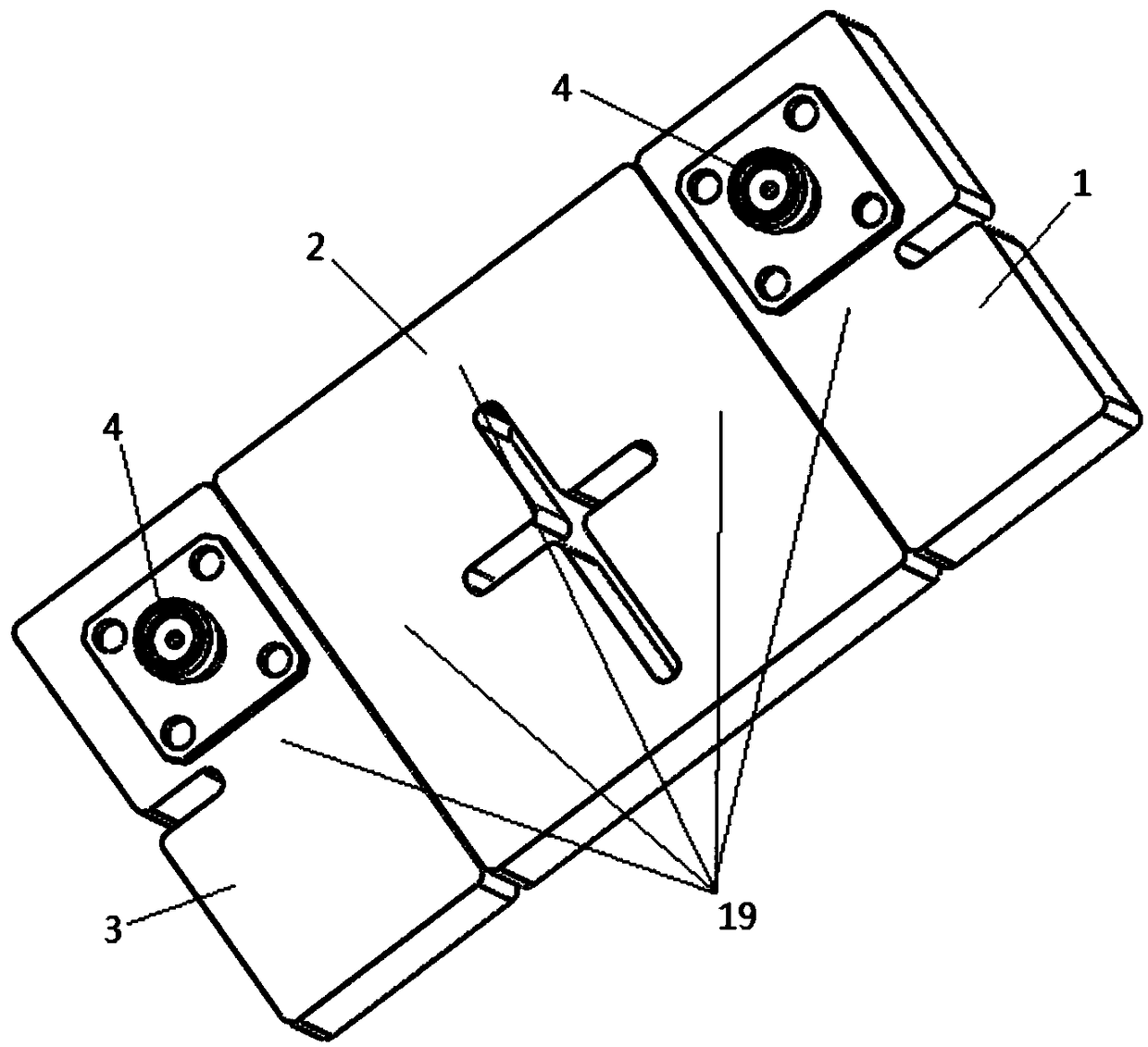
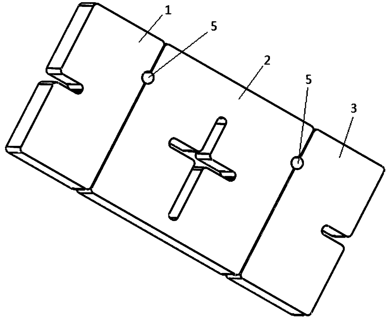
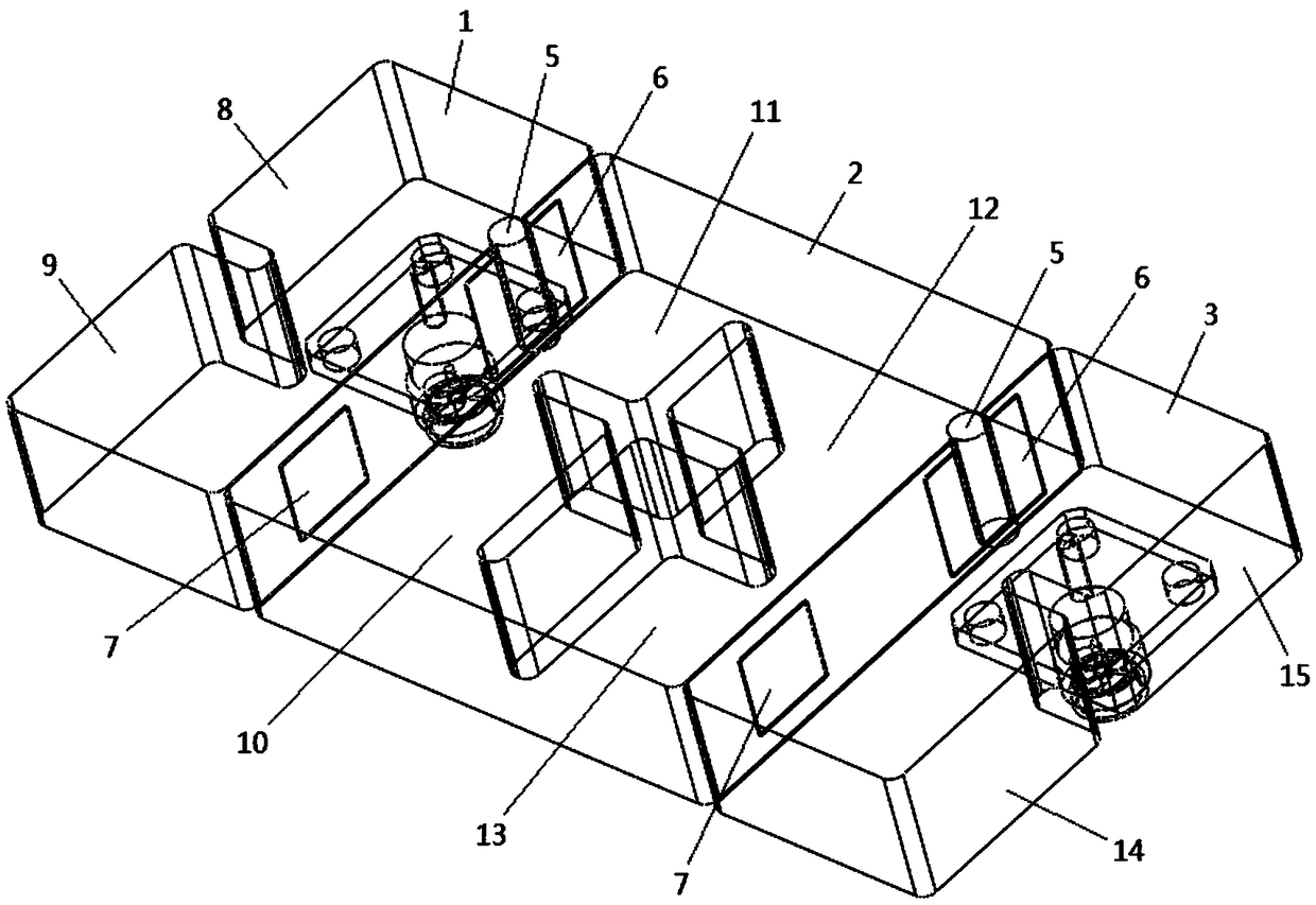
[0045] Such as Figure 1-4As shown, the capacitive coupling device of this embodiment includes three dielectric monomers, namely the first dielectric monomer 1, the second dielectric monomer 2 and the third dielectric monomer 3, and the three dielectric monomers are spliced ​​and connected Form a linear structure, the first dielectric monomer 1 and the third dielectric monomer 3 include two dielectric single cavities, the second dielectric monomer 2 includes four dielectric single cavities, the first dielectric monomer 1 and the second dielectric monomer Between the dielectric single chambers 9 and 10 on 2, and between the dielectric single chambers 13 and 14 on the second dielectric unit 2 and the third dielectric unit 3 are all coupled through the second air coupling window 7 provided on the splicing surface, The medium single cavities 8-15 on the three dielectric monomers form the main coupling channel 16, and the two non-adjacent medium single cavities (such as between the...

Embodiment 2

[0047] Such as Figure 5-8 As shown, the difference between this embodiment and Embodiment 1 is that the arrangement of the three dielectric cells is different. The capacitive coupling device of this embodiment includes three dielectric cells, namely the first dielectric cell 1, the second dielectric cell Dielectric monomer 2 and third dielectric monomer 3, the three dielectric monomers are spliced ​​and connected to form a character-shaped structure, the first dielectric monomer 1 and the third dielectric monomer 3 include two dielectric single chambers, and the second dielectric monomer The cell 2 includes three medium single cavities, between the first medium cell 1 and the medium single cavity on the second medium cell 2, between the medium single cavity on the second medium cell 2 and the third medium cell 3 Both of them are coupled through the second air coupling window 7 provided on the splicing surface, and the dielectric single cavities 8-14 on the three dielectric mo...

Embodiment 3

[0049] Such as Figure 9-12 As shown, the capacitive coupling device of this embodiment includes eight dielectric monomers, and the eight dielectric monomers are spliced ​​and connected, wherein four adjacent dielectric monomers form a cross-shaped structure, and the eight dielectric monomers are each Only one dielectric single cavity is included, and the eight dielectric single cavities 8-15 are coupled through the second air coupling window 7 provided on the splicing surface to form the main coupling channel 16. The two non-adjacent dielectric single cavities in the main coupling channel The first blind hole 5 and the first air coupling window 6 provided on the splicing surface form a capacitive coupling between the dielectric single cavities 10 and 13, thereby generating a transmission zero at the low end and high end of the passband. The center of each dielectric single cavity is provided with a second blind hole 17 for frequency tuning, and the inner wall and bottom of th...


PUM


Abstract

The invention discloses a capacitive coupling device and a filter. The capacitive coupling device comprises a plurality of solid media monomers, the adjacent media units are spliced together, At leastone adjacent dielectric monome is provided with a capacitively couple structure on that splicing surface, the capacitive coupling structure includes a first blind hole and a first air coupling windowwith a surface unmetallized, The depth of the first blind hole is greater than or equal to 1/2 of the depth of the first air coupling window and less than the depth of the first air coupling window,a metal shielding layer is arranged on the inner wall of the first blind hole, and the first air coupling window is arranged on the two sides and the bottom of the first blind hole. Blind holes and air coupling windows are arranged on the splicing surface to realize coupling between the two cavities. The transmission zero can be formed at the low end of the pass band of the filter, and the rectangular coefficient of the filter is increased, thereby improving the filter performance and reducing the volume of the filter.

Description

technical field [0001] The invention belongs to the technical field of communication, and in particular relates to a capacitive coupling device and a filter. Background technique [0002] In the field of mobile communication, with the development of technology, the performance requirements of filters in the system are getting higher and higher. With the improvement of requirements, the high-power microwave filter at the base station has the characteristics of high index, small size and low cost. When realizing these high-performance filters, limited by the size of the cavity, the filters need to be realized using new materials or technologies. [0003] Limited by the material characteristics of the dielectric filter, it is generally necessary to add a transmission zero point when designing the filter. Dielectric filters are more difficult to achieve capacitive cross-coupling than metal filters. Among the existing designs, Patent No. 201310688407.3 discloses three possible...

Claims


Application Information

Patent Timeline
Patent Type & Authority Applications(China)
IPC IPC(8): H01P1/208
CPCH01P1/208
Inventor 许建军朱晖
Owner WUHAN FINGU ELECTRONICS TECH
Why Eureka
Try Eureka