Oblique projector having movable free form lenses

a projector and free-form technology, applied in the direction of printers, instruments, camera focusing arrangement, etc., can solve the problems of further shortening of the projection distance and the need for miniaturization of the projection optic system, and achieve the effect of shortening the projection distance and miniaturizing the projection optic system

Active Publication Date: 2013-12-31
MAXELL HLDG LTD
View PDF24 Cites 12 Cited by
  • Summary
  • Abstract
  • Description
  • Claims
  • Application Information

AI Technical Summary

Benefits of technology

[0005]According to the prior art, in the projection optic system using the focusing lenses, a large projection image is obtained with a short projection distance (a distance from the object plane (image display element surface) to the principal point of the free-form-surface mirror 23 is 327.6 mm, a distance from the principal point of the free-form-surface mirror 23 to the image plane is 567 mm, and the image is 80 inches). However, further shortening of the projection distance and miniaturization of the projection optic system are required.

Problems solved by technology

However, further shortening of the projection distance and miniaturization of the projection optic system are required.

Method used


Image

  • Oblique projector having movable free form lenses
  • Oblique projector having movable free form lenses
  • Oblique projector having movable free form lenses

Examples


Embodiment Construction

[0021]Embodiments of the present invention are now described with reference to the accompanying drawings.

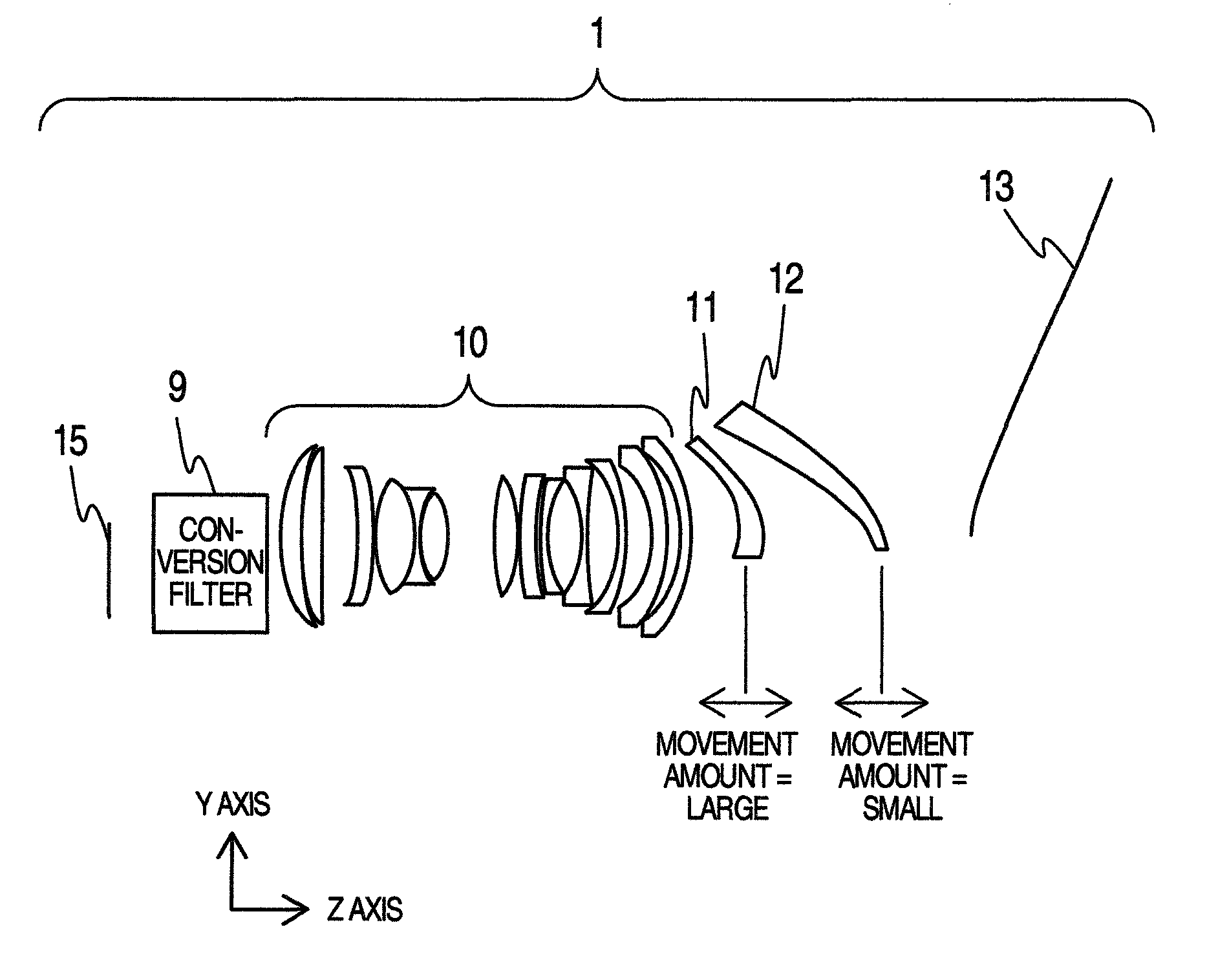
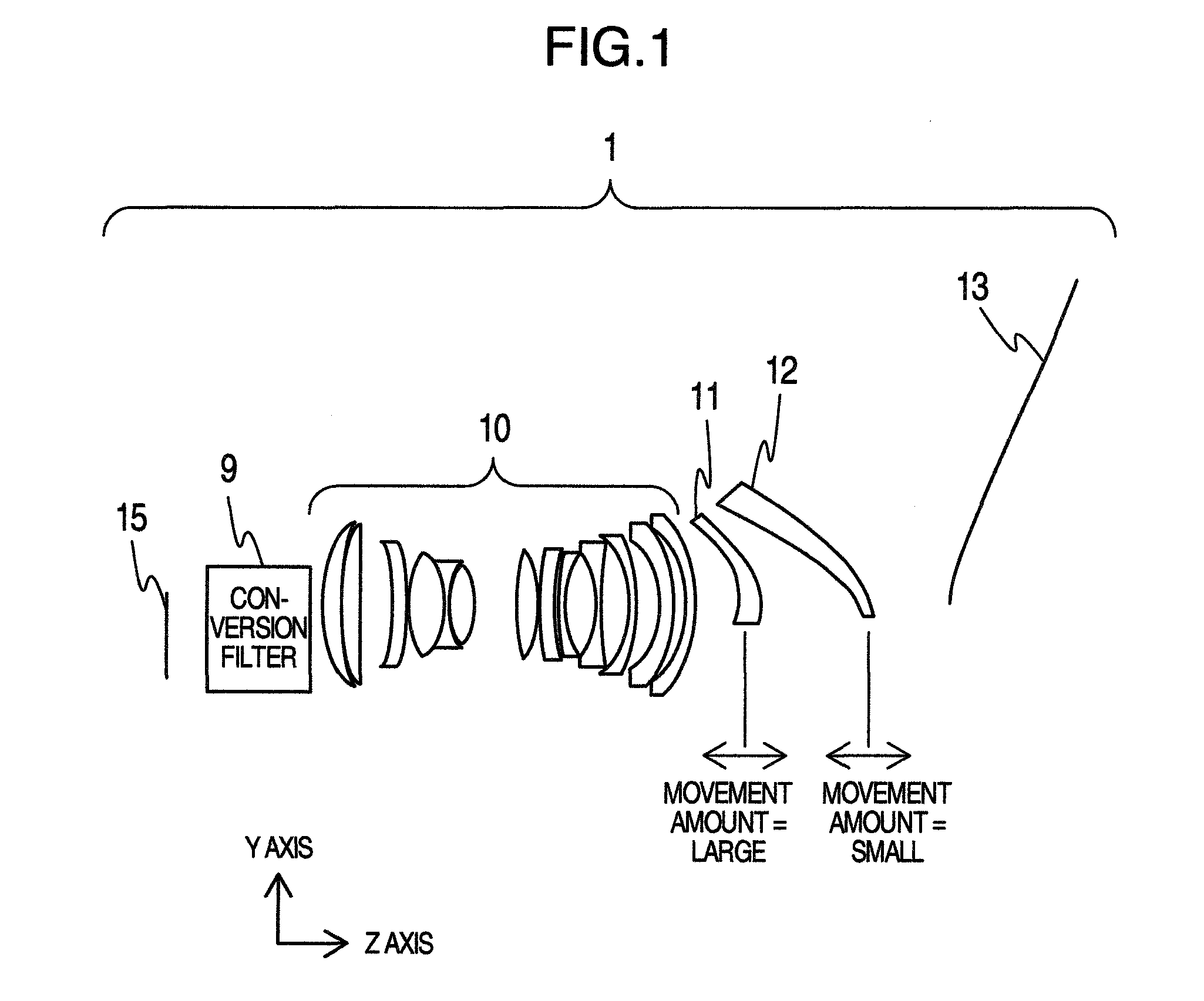
[0022]First, referring to FIGS. 4A and 4B, a basic composition and the effect of angle-of-view widening of a wide-conversion lens are described. FIG. 4A illustrates a focal distance f1 of a primary lens 200 in case where there is no wide-conversion lens 100. A luminous flux from infinity is focused on a focal point of the primary lens 200. On the other hand, FIG. 4B is a schematic diagram illustrating a composition in which a wide-conversion lens 100 is disposed on the image plane side of the primary lens 200. A luminous flux from infinity is pushed up by a concave lens 112 of the wide-conversion lens 100 and returned to a collimated luminous flux by a convex lens 111 to be focused on the focal point of the primary lens 200. Actually, the primary lens 200 is designed to have a predetermined F-number and, when observed from the image display element side, a collimated light to ent...


PUM


Abstract

A projection type image display apparatus in which shortening of the projection distance (widening of the angle of view) and miniaturization of the projection optic system are realized is provided. It comprises, in a traveling direction of the light, an image display element, a lens group including a plurality of lenses, a first lens, a second lens, and a mirror to reflect light emitted from the second lens to be projected obliquely on a screen in this order. The refractive power of the first lens is positive and the refractive power of the second lens is negative. The first and the second lenses are moved in an interlocked relationship with each other along an optical axis of the lens group and a movement amount of the first lens is made larger than a movement amount of the second lens.

Description

INCORPORATION BY REFERENCE[0001]The present application claims priority from Japanese application JP2010-126436 filed on Jun. 2, 2010, the content of which is hereby incorporated by reference into this application.BACKGROUND OF THE INVENTION[0002]The present invention relates to a projection type image display apparatus.[0003]In a prior art, a projection optic system (FIG. 8) using one free-form-surface mirror and two free-form-surface lenses and technique (FIG. 9) in which the two free-form-surface lenses thereof are moved in an interlocked relationship with each other for focusing are known (refer to JP-A-2010-72374 and JP-A-2009-109867).[0004]FIG. 10A is a schematic diagram which extracts free-form-surface lenses functioning as focusing lenses and a fixed lens disposed before the lenses and FIG. 10B is a schematic diagram illustrating movement loci of the free-form-surface lenses functioning as focusing lenses, that is, a cam diagram. In FIGS. 10A and 10B, the smaller an image pr...

Claims


Application Information

Patent Timeline
Patent Type & Authority Patents(United States)
IPC IPC(8): G03B21/26G03B21/14G02B15/14G03B21/20G03B3/00G02B9/00G02B3/00
CPCG02B13/16G02B13/18G02B17/0852G02B15/177G02B15/1421
Inventor YATSU, MASAHIKO
Owner MAXELL HLDG LTD
Why Eureka
Try Eureka