Continuously-variable transmission for vehicle

a transmission and vehicle technology, applied in mechanical equipment, gears, instruments, etc., can solve the problem that the cooperative shift is not expected to suppress the shift shock, and achieve the effect of improving the shift quality, enhancing the speed-ratio width, and facilitating vehicle star

Active Publication Date: 2013-12-31
JATCO LTD +1
View PDF11 Cites 8 Cited by
  • Summary
  • Abstract
  • Description
  • Claims
  • Application Information

AI Technical Summary

Benefits of technology

[0005]The cooperative shift for maintaining the through speed ratio at a constant level is effective in suppressing the shift shock during a phase called “inertia phase” which is a part of the shift transient period of auxiliary transmitting mechanism and for which the input rotational speed varies. However, this cooperative shift is not expected to suppress a shift shock in the “torque phase” for which the input rotational speed does not vary.
[0007]It is therefore an object of the present invention to provide a continuously-variable transmission for a vehicle, devised to improve the shift quality at the time of shift of auxiliary transmitting mechanism while realizing the enlargement of speed-ratio width which attains a favorable responsiveness of vehicle start and a favorable energy saving.
[0008]According to one aspect of the present invention, there is provided a continuously-variable transmission for a vehicle, comprising: a belt-type continuously-variable transmitting mechanism connected to a drive source and configured to continuously vary a speed ratio of the belt-type continuously-variable transmitting mechanism; an auxiliary transmitting mechanism provided in series with the belt-type continuously-variable transmitting mechanism and configured to attain a plurality of shift steps for a forward running of the vehicle; and a speed-increasing gear mechanism provided upstream from the auxiliary transmitting mechanism and configured to increase an input rotational speed of the auxiliary transmitting mechanism.

Problems solved by technology

However, this cooperative shift is not expected to suppress a shift shock in the “torque phase” for which the input rotational speed does not vary.
Accordingly, there has been a problem that a shift shock called “pull-in shock (depression shock)” occurs so as to largely damage a shift quality, due to the reduction of output-shaft torque during the “torque phase” at the time of shift of auxiliary transmitting mechanism.

Method used


Image

  • Continuously-variable transmission for vehicle
  • Continuously-variable transmission for vehicle
  • Continuously-variable transmission for vehicle

Examples


first embodiment

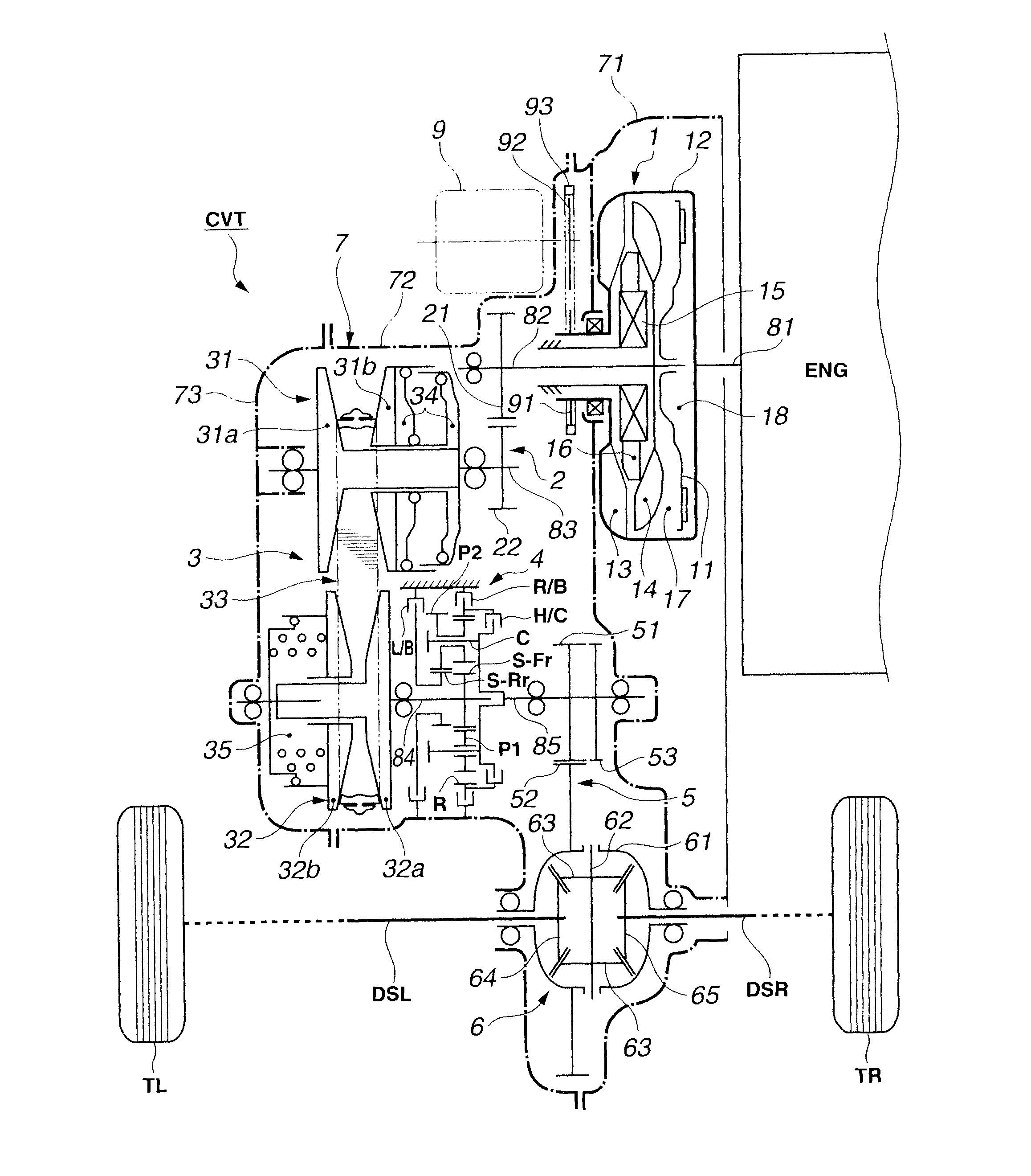
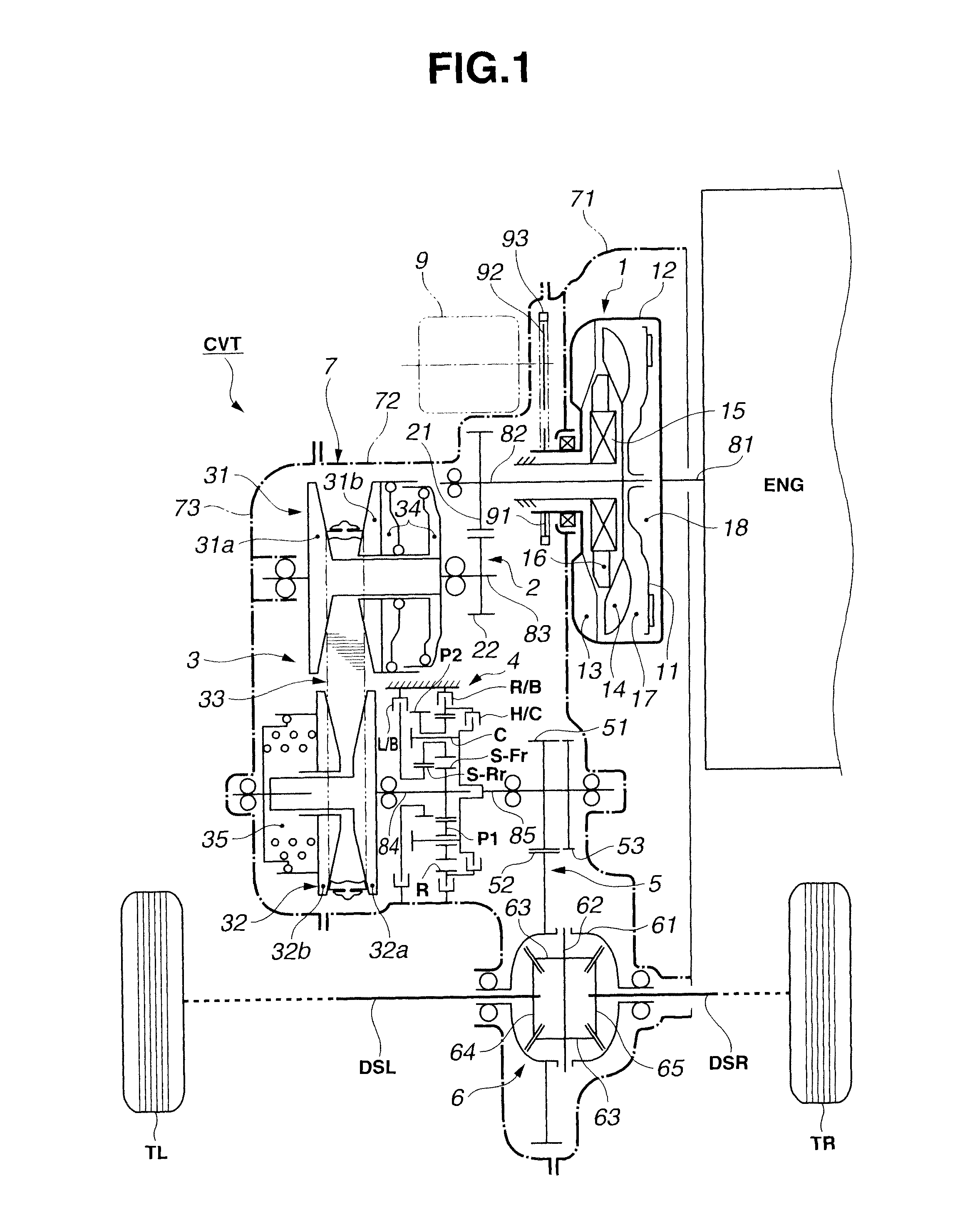
[0022]At first, a configuration according to a first embodiment of the present invention will be explained. FIG. 1 is a schematic view showing an engine vehicle equipped with a continuously-variable transmission CVT according to the first embodiment. Hereinafter, a schematic configuration of the engine vehicle and a configuration of the continuously-variable transmission CVT will now be explained referring to FIG. 1.

[0023]As shown in FIG. 1, in the engine vehicle equipped with the continuously-variable transmission CVT according to the first embodiment; an engine ENG (drive source) is connected to an input-side portion of the continuously-variable transmission CVT, and a left drive shaft DSL and a right drive shaft DSR are connected to an output-side portion of the continuously-variable transmission CVT. A left drive wheel (road-wheel) TL is attached to an end portion of the left drive shaft DSL, and a right drive wheel TR is attached to an end portion of the right drive shaft DSR.

[...


PUM


Abstract

A continuously-variable transmission for a vehicle includes a belt-type continuously-variable transmitting mechanism connected to a drive source and configured to continuously vary a speed ratio of the belt-type continuously-variable transmitting mechanism; an auxiliary transmitting mechanism provided in series with the belt-type continuously-variable transmitting mechanism and configured to attain a plurality of shift steps for a forward running of the vehicle; and a speed-increasing gear mechanism provided upstream from the auxiliary transmitting mechanism and configured to increase an input rotational speed of the auxiliary transmitting mechanism.

Description

BACKGROUND OF THE INVENTION[0001]The present invention relates to a continuously-variable transmission for a vehicle, which includes a belt-type continuously-variable transmitting mechanism and an auxiliary transmitting mechanism disposed in series with the belt-type continuously-variable transmitting mechanism.[0002]Japanese Patent Application Publication No. 60-037455 (corresponding to UK Patent Application Publication No. 2144814) discloses a previously-proposed continuously-variable transmission for a vehicle. In this technique, an auxiliary transmitting mechanism that can attain two shift steps (two speed ratios) for forward running of vehicle is provided in series with a belt-type continuously-variable transmitting mechanism, and the shift step of this auxiliary transmitting mechanism is changed according to a running state of vehicle. Thereby, obtainable range of speed ratio (i.e., obtainable speed-ratio width) of whole of the continuously-variable transmission is made larger...

Claims


Application Information

Patent Timeline
Patent Type & Authority Patents(United States)
IPC IPC(8): G06F7/00
CPCF16H61/66259F16H2037/023F16H37/022F16H61/6625
Inventor URATA, TAKESHINAKANO, HARUHISA
Owner JATCO LTD
Why Eureka
Try Eureka