
Natural gas analyzer on a micro-chip

a micro-chip and natural gas analyzer technology, applied in the direction of dispersed particle separation, instruments, separation processes, etc., can solve the problems of limiting the adaptability and versatility of equipment, consuming a lot of resources, and wasting a lot of time and assets

Active Publication Date: 2014-01-07
SCHLUMBERGER TECH CORP
View PDF19 Cites 10 Cited by
  • Summary
  • Abstract
  • Description
  • Claims
  • Application Information

AI Technical Summary

Benefits of technology

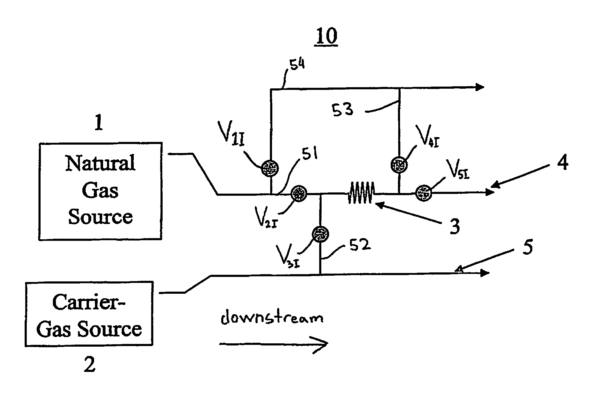
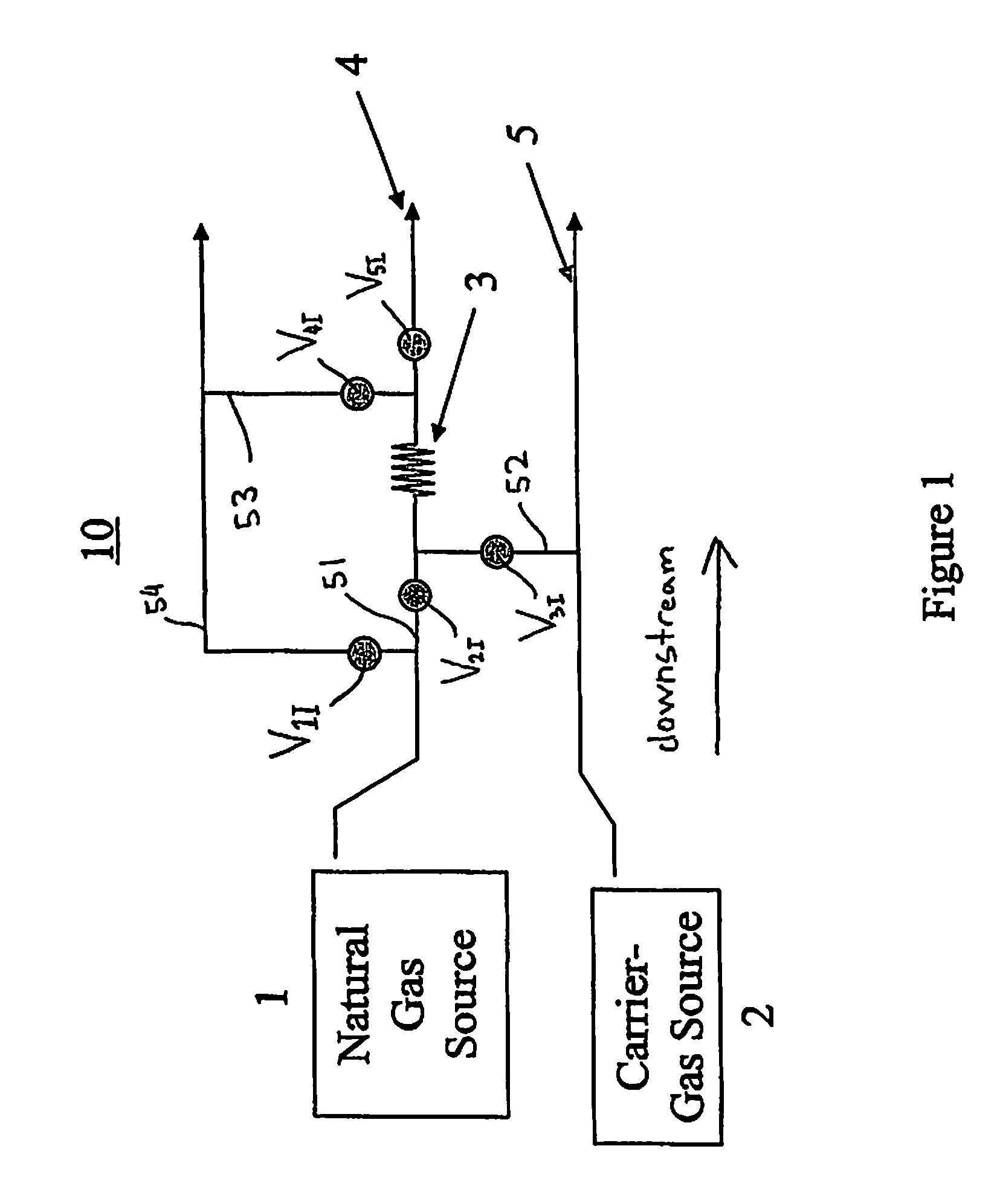
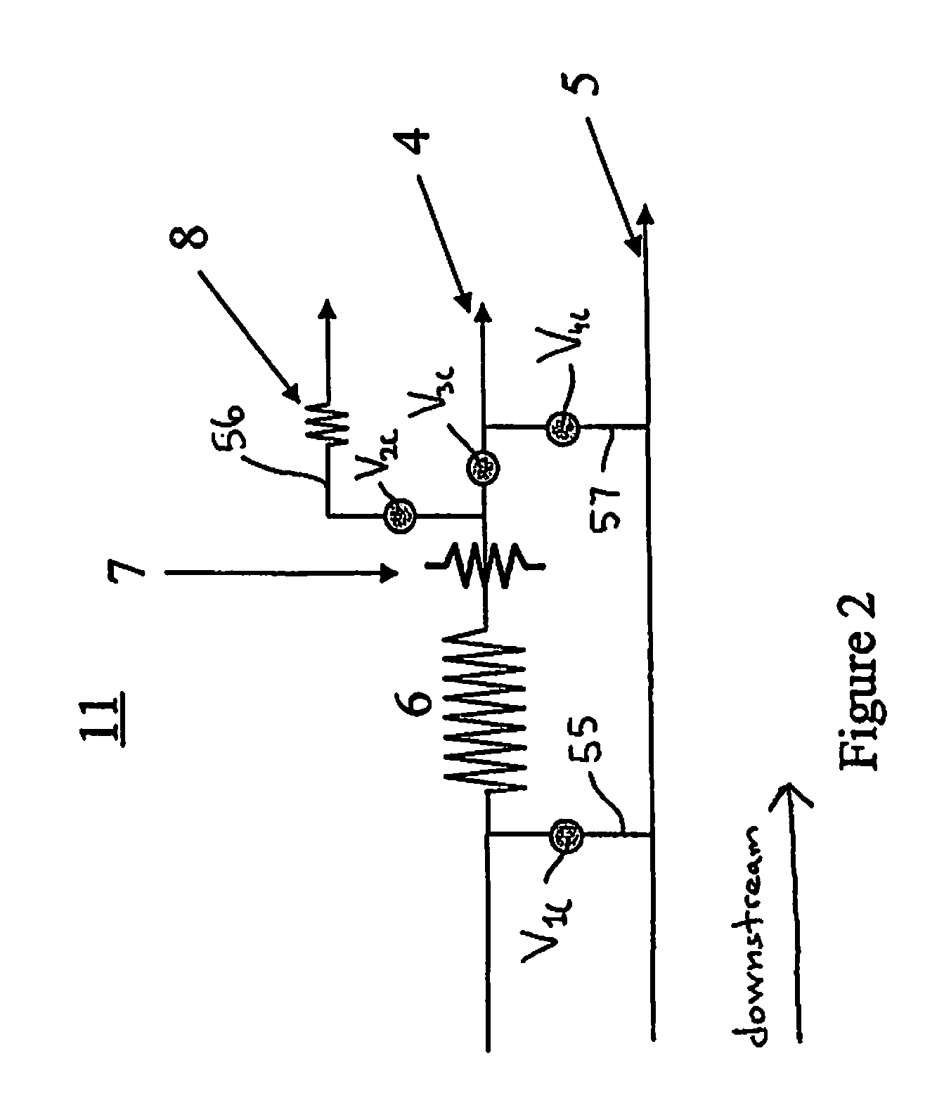
The patent is about a miniaturized gas analyzer that can be made onto a micro-chip. This analyzer has an injector block that collects the gas sample and expels it with carrier-gas, along with a separation column that separates the gas sample into different components. A detector then receives the separated components and identifies them as resolved or unresolved. The injector block and columns are arranged in series, so the gas sample is first received in the injector and then separated in the first column before being received in the second column for further analysis. The method using this analyzer involves sampling natural gas and injecting the gas sample into the injector, which is then separated and analyzed using the columns. Overall, the invention allows for the efficient and accurate analysis of gas samples.

Problems solved by technology

For example, the equipment used for gas chromatographs within laboratories has remained fairly large and cumbersome, thereby limiting the adaptability and versatility for the equipment.
These limitations may be a strain on resources, as moving the equipment around may be a challenge that requires an unnecessary amount of time and assets.
Because of the bulkiness of the existing GC analyzers for gas analysis this analysis is typically performed off-line in a laboratory environment.
Though Schmidt describes a smaller gas chromatograph for manufacturing, the chromatographs are still slow to develop for use within the natural gas industry.
As such, this suggests that these domestic gas chromatographs are designed to analyze only a small portion of the natural gas spectrum, therefore not being useful or applicable outside of this small application.
This large variation within the ranges of the components of natural gas makes it difficult for gas chromatographs to correctly separate and analyze the components within the natural gas.

Method used


Image

  • Natural gas analyzer on a micro-chip
  • Natural gas analyzer on a micro-chip
  • Natural gas analyzer on a micro-chip

Examples


Embodiment Construction

[0018]Specific embodiments of the present invention will now be described in detail with reference to the accompanying figures. Like elements in the various figures may be denoted by like reference numerals for consistency.

[0019]In the following detailed description of embodiments of the present disclosure, numerous specific details are set forth in order to provide a more thorough understanding of the invention. However, it will be apparent to one of ordinary skill in the art that the present invention may be practiced without these specific details. In other instances, well-known features have not been described in detail to avoid unnecessarily complicating the description.

[0020]As used herein, the embodiments disclosed herein are described for separating components from a gas sample of natural gas. However, those having ordinary skill in the art will appreciate that any composite gas known in the art, and not only natural gas, may be used to be separated into smaller components o...


PUM

PropertyMeasurementUnit
lengthsaaaaaaaaaa
lengthsaaaaaaaaaa
lengthsaaaaaaaaaa

Abstract

A miniaturized gas analyzer formed onto a micro-chip and a method of separating components from a composite gas using the miniaturized gas analyzer are disclosed. The gas analyzer includes an injector block and two column blocks arranged in series along an analytical path. The injector block receives the composite gas and a carrier gas to create a gas sample. The gas sample is then injected into the column blocks to separate the components of the composite gas. Further, a valve used within the miniaturized gas analyzer is disclosed, in which the valve is formed onto the micro-chip and includes a flexible membrane and a rigid substrate.

Description

CROSS-REFERENCE TO RELATED APPLICATIONS[0001]The present application is based on and claims priority to EP Application No. 07291432.8, filed 30 Nov. 2007; and International Patent Application No. PCT / EP2008 / 009700, filed 17 Nov. 2008. The entire contents of each are herein incorporated by reference.BACKGROUND[0002]1. Field of the Disclosure[0003]The invention generally relates to miniaturized natural gas analyzers that use gas chromatography. Specifically, it relates to a natural gas analyzer that is machined onto a single micro-chip and uses gas chromatography for analyzing natural gas.[0004]2. Background Art[0005]Gas chromatography (GC) has been used for more than 50 years within the field of natural gas analysis to separate and quantify the different components found within natural gas. Over this time period, the technology used within gas chromatographs has generally remained the same since when the technology was originally introduced into the natural gas industry. For example,...

Claims


Application Information

Patent Timeline
Patent Type & Authority Patents(United States)
IPC IPC(8): B01D53/14G01N30/02G01N30/04
CPCG01N30/6095G01N2030/207G01N2030/025G01N30/465G01N30/461
Inventor GUIEZE, PAUL
Owner SCHLUMBERGER TECH CORP
Learn More