Seal assembly and method for forming a seal assembly

a seal assembly and sealing technology, applied in the direction of couplings, rod connections, manufacturing tools, etc., can solve the problems of curtail the service life of the seal assembly, the seal configuration has not shown a satisfactory service life, and the strain reduction

Active Publication Date: 2014-01-07
CATERPILLAR INC
View PDF14 Cites 10 Cited by
  • Summary
  • Abstract
  • Description
  • Claims
  • Application Information

AI Technical Summary

Problems solved by technology

The seal assemblies deform during the transverse, pivotal movement which may curtail the service life of the seal assemblies.
Such a seal configuration has not shown a satisfactory service life when exposed to the pivotal movements experienced during operation of the machine.
While radial swaging may effectively reduce some seal strain during operation, such strain reduction may be insufficient for certain applications where the seals may experience significant deformation, requires at least one extra step during manufacturing, and is overly costly.

Method used


Image

  • Seal assembly and method for forming a seal assembly
  • Seal assembly and method for forming a seal assembly
  • Seal assembly and method for forming a seal assembly

Examples


Embodiment Construction

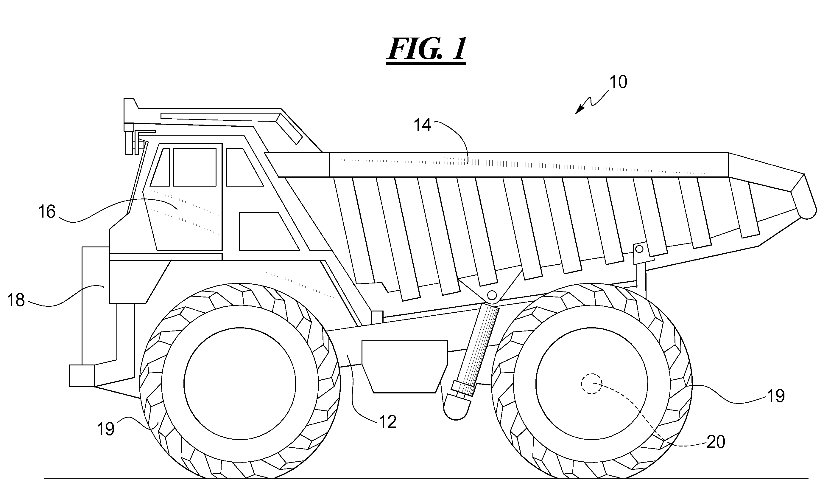
[0034]FIG. 1 illustrates a machine such as an off-highway truck 10. The machine 10 may have any suitable construction, and may include a frame 12 and an implement such as a material carrying dump body 14 pivotally mounted to the frame 12. An optional operator cab 16 may be mounted on the front of the frame 12 above a power system enclosure such as an engine enclosure 18. One or more power sources such as turbines, engines, batteries, fuel cells, or capacitors (not shown) may be housed within the engine enclosure 18 to provide power to a plurality of wheels 19, which support the truck on the ground. A rear axle 20 may be coupled to and rotatable with the wheels 19, and may be driven by the power source.

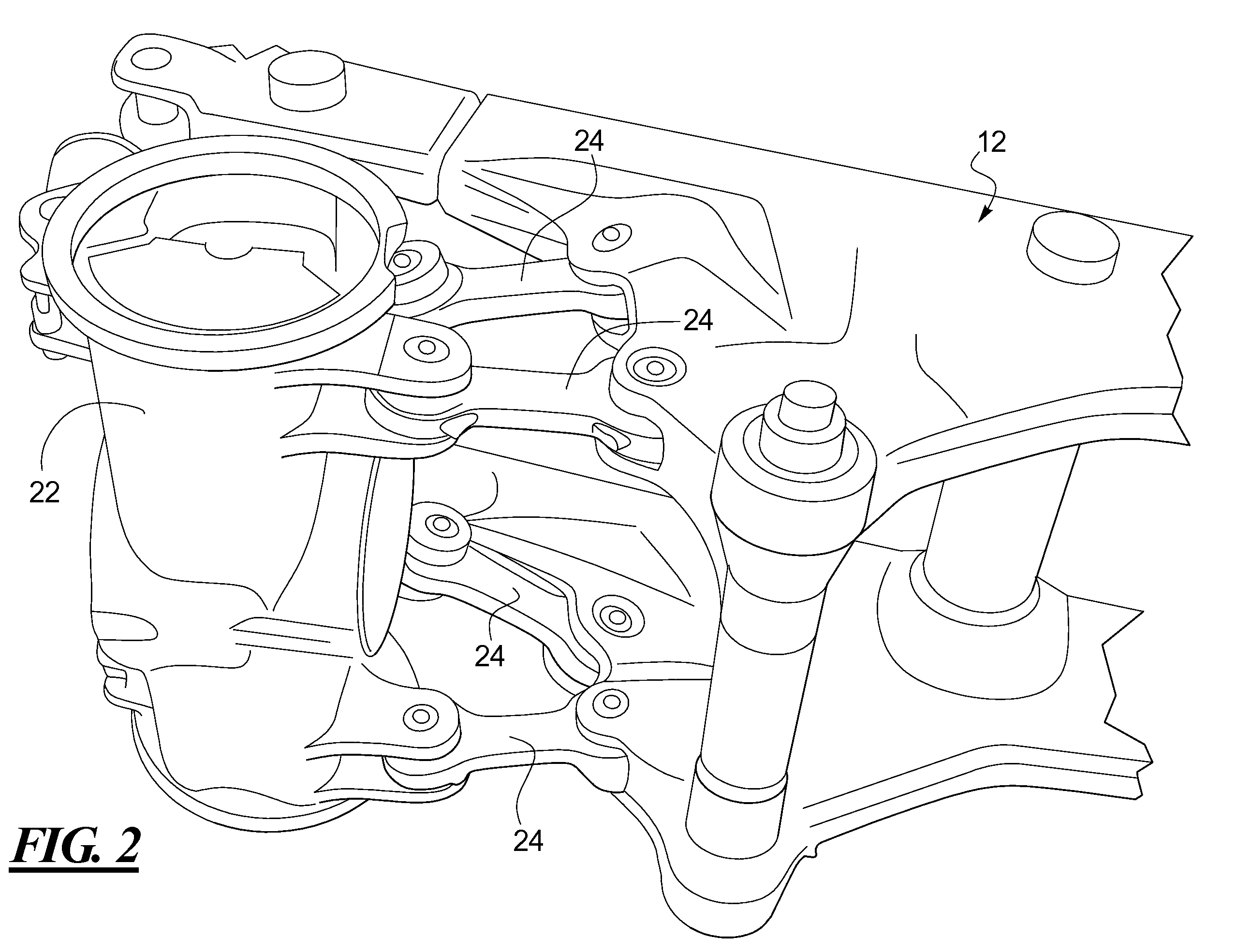
[0035]The rear axle 20 may be carried by an axle housing 22 suspended from the frame 12. Optionally and as best shown in FIG. 2, the axle housing 22 may be coupled to the frame by a four bar link suspension including four links 24. Each link 24 includes a first end pivotally coupled to...


PUM

PropertyMeasurementUnit
thicknessaaaaaaaaaa
offset distanceaaaaaaaaaa
angleaaaaaaaaaa

Abstract

A seal assembly and method of forming a seal assembly provides a seal body having reduced strain during use, thereby increasing service life. The seal body may be formed within certain parameters, such as ranges of height-to-thickness and offset-to-height ratios, which have been found to reduce strain. Additionally or alternatively, the seal body may be modified from an initial configuration to a pre-strained configuration by axially displacing an inner section of the seal with respect to an outer section of the seal, which also reduces strain.

Description

CROSS-REFERENCE TO RELATED APPLICATION[0001]This application claims the benefit of U.S. Provisional Application No. 61 / 349,369, filed May 28, 2010.TECHNICAL FIELD[0002]This disclosure relates generally to seal assemblies used on flexible joints and methods for forming such seal assemblies.BACKGROUND[0003]Flexible joints are used in a variety of apparatus, such as machines, to connect components that may move relative to one another. One type of flexible joint is a spherical joint, wherein two components are connected for compound movements by a semi-spherical bearing having a journal mounted therein. A pair of annular seal assemblies may be disposed on either side of the journal to protect the joint from debris or damage from the environment.[0004]Sealing may be particularly advantageous when the joint is used in certain applications, such as on off-highway machines where the environment may include high levels of dust and debris. A mining truck, for example, may use a four bar link...

Claims


Application Information

Patent Timeline
Patent Type & Authority Patents(United States)
IPC IPC(8): F16C11/06
CPCF16C11/045F16C11/0671F16C11/0614F16C33/74F16J15/52Y10T403/31Y10T403/32951Y10T403/32729
Inventor BECKER, DAN J.WIETHARN, ROSS PAUL
Owner CATERPILLAR INC
Why Eureka
Try Eureka