Disc filtration device

a filtration device and disc technology, applied in the direction of gravity filters, loose filtering material filters, cartridge filters, etc., can solve the problems of mechanical deformation, high risk, and risk of dismounting, and achieve the effect of eliminating the risk of falling, stable mechanical behaviour, and easy maintenance of the filtration facility

Active Publication Date: 2014-01-14
GAUDFRIN
View PDF20 Cites 4 Cited by
  • Summary
  • Abstract
  • Description
  • Claims
  • Application Information

AI Technical Summary

Benefits of technology

[0015]According to another alternative embodiment specific to the maintenance, the detachable part of the ring is disengaged, the connection flanges corresponding to the sectors to be replaced are released, then the sectors are removed one after the other by slightly inclining the same and taking the tips out of the offtakes, while installing simultaneously and at the same time new sectors so that the rim (2) remains permanently supported. The device of the invention allows an easy maintenance of the filtration facility by enabling the replacement of a sector independently of the others and this without any quarter turn or dismounting of the rim.
[0016]In addition, the method of the invention thus eliminates the risks of falls for the rim elements or deformation of the sectors upon the steps of filling of the disc by providing a stable mechanical behaviour of the latter prior to the mounting of said sectors and by enabling the positioning thereof without requiring the quarter turn to lock it in the ring. Thus, mounting operations can be carried out by only one operator. The rim is thus mounted once and for all. Thanks to the new fixation and locking mode of the sectors which releases the rim not only from the weight of the sectors and the filtration cakes thereof, but also from any accidental mounting mechanical constraints, thanks more particularly to a quick spring coupling, the rim thus transfers to the disc a greater rigidity and a better behaviour which are all the more required as the disc has large dimensions.
[0016]In addition, the method of the invention thus eliminates the risks of falls for the rim elements or deformation of the sectors upon the steps of filling of the disc by providing a stable mechanical behaviour of the latter prior to the mounting of said sectors and by enabling the positioning thereof without requiring the quarter turn to lock it in the ring. Thus, mounting operations can be carried out by only one operator. The rim is thus mounted once and for all. Thanks to the new fixation and locking mode of the sectors which releases the rim not only from the weight of the sectors and the filtration cakes thereof, but also from any accidental mounting mechanical constraints, thanks more particularly to a quick spring coupling, the rim thus transfers to the disc a greater rigidity and a better behaviour which are all the more required as the disc has large dimensions.

Problems solved by technology

But the construction of such devices raises the problem of positioning tolerance of the pin of the pipe in the sectors which are consequently exposed to a risk of mechanical deformation.
This risk is all the higher since the rotation thereof during the quarter turn required for the positioning thereof is forced.
The problem of holding curvilinear elements composing the rim during the assembling thereof, which consequently becomes difficult and is exposed to risks of dismounting before all the elements are connected together, also arises.
Another drawback lies in the utilisation of threaded screws in the rim to wedge the sectors therebetween.
Such screws do not make it possible to master the stresses caused on the sectors as well as on the rim nor to distribute the same appropriately over the whole disc.
Now, such stresses cause deformations or even breaks in the sectors as well as in the rim.
Such drawback is all the more tangible when it concerns the construction of very large discs which must, however, have a light structure required for the manual assembling of the sectors.
In addition, such prior devices do not allow an easy maintenance because the replacement of only one or several used or damaged filtering sectors requires the dismounting of the rim to extract the pipe of the sector from the embedding thereof in the shaft.

Method used


Image

  • Disc filtration device
  • Disc filtration device
  • Disc filtration device

Examples


Embodiment Construction

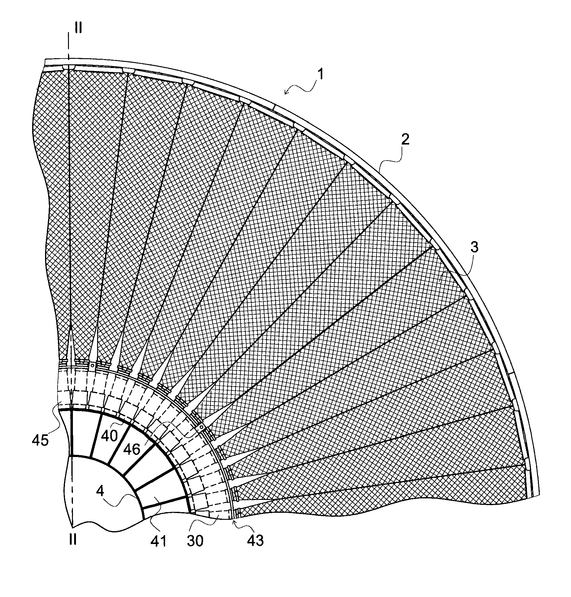
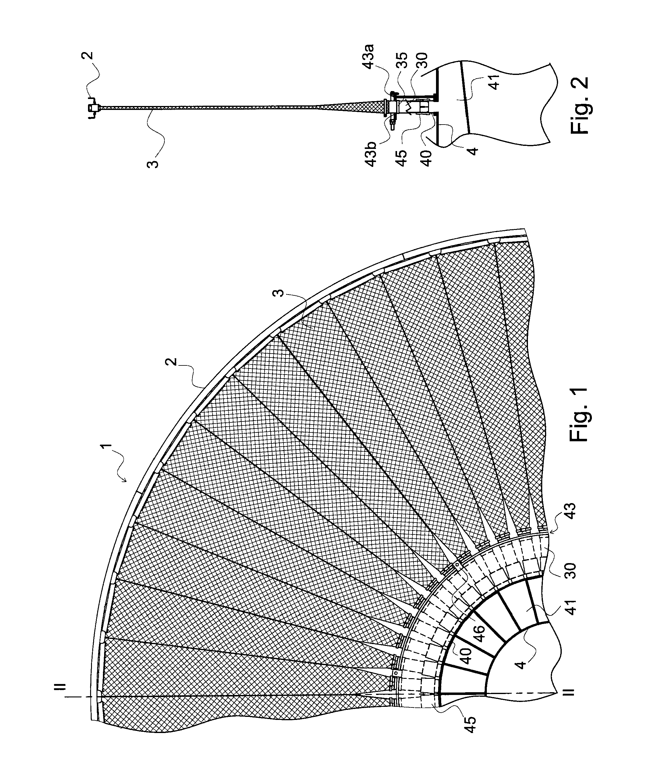
[0031]The filter device shown in FIGS. 1 and 2 includes a disc 1 provided with a rim 2 holding a plurality of filtering sectors 3. The sectors 3 are each composed of a triangular frame 31 made of a U-shaped section inserting a structure 32 in charge of draining the filtrates towards the outlet 30 provided with a tip 33, as shown more particularly in FIGS. 4A to 4C, 7A and 7B.

[0032]The sectors 3 are introduced into and accommodated in a triangular pocket 34 made from a filtering cloth opened at the base of the triangle. This pocket is further closed by folding the cloth on either side of the external edge of the sector and by wedging the cloth using a cloth clip 8 in the corner using the structure 32 supporting the cloth and the U-shaped frame 31 of the sector 3 which covers same as shown in FIG. 7B. The cloth clip 8 is made with a U-shaped section the sides of which form a jaw 82, such jaw extends almost up to the frame 31 of the sector so that it will be folded on the structure onl...


PUM

PropertyMeasurementUnit
stressaaaaaaaaaa
elasticaaaaaaaaaa
thicknessaaaaaaaaaa

Abstract

The disclosure relates to a filtration device that comprises a disc with a rim covering and stiffening a plurality of filtration sectors connected to taps provided on the outer wall of a rotary main shaft containing inner discharge channels and fit-inserted into said taps and into a crown comprising two parts concentric to the shaft, one which is secured to the shaft while the other is removable, characterised in that said rim is provided with openings each intended for receiving a removable connection flange bearing, on the one hand, a radial strut clamped between two adjacent sectors for the relative clamping thereof and interacting, on the other hand, with a spring quick fastener for locking the strut under tension between the sectors. The disclosure also relates to a method for assembling and maintaining said filtration device.

Description

CROSS-REFERENCE TO RELATED APPLICATIONS[0001]This application is a National Phase Entry of International Application No. PCT / FR2007 / 001575, filed on Sep. 26, 2007, which is incorporated by reference herein.BACKGROUND AND SUMMARY[0002]The present invention relates to a disc filtration device and the assembling and maintenance methods therefor.[0003]Among the devices used for the liquid / solid separation of a loaded suspension on an industrial scale, large diameter discs more particularly exist which are provided with a rim capping and rigidifying a plurality of filtering sectors by surrounding them. Such sectors are generally covered with a cloth and provided with pipes which are likely to be connected to the external wall of a rotating central shaft by opening into internal outlet channels for the filtered liquid. Such discs are vertically positioned and rotated, with their lower parts being immerged in tanks containing the suspensions to be filtered, whereas the internal channels of...

Claims


Application Information

Patent Timeline
Patent Type & Authority Patents(United States)
IPC IPC(8): B01D25/00B01D33/00B01D29/00B01D35/16B01D35/12B01D35/30B01D35/22B01D24/00B01D39/00B01D27/00
CPCB01D33/23Y10T137/0402B01D33/803
Inventor GAUDFRIN
Owner GAUDFRIN
Why Eureka
Try Eureka