Cavity backed cross-slot antenna apparatus and method

a cross-slot antenna and cavity-back technology, applied in the direction of antenna details, slot antennas, antennas, etc., can solve the problems of not being able to use a conventional slot antenna and putting too little energy down the sales area of the stor

Active Publication Date: 2014-01-14
SYMBOL TECH LLC
View PDF16 Cites 9 Cited by
  • Summary
  • Abstract
  • Description
  • Claims
  • Application Information

AI Technical Summary

Problems solved by technology

However, this is not possible for a conventional slot antenna 20 as depicted in a top view in FIG. 2 and a side view in FIG. 3.
That kind of antenna in this application would place an undesirable amount of signal in directions that would illuminate the materials within the drop ceiling, and place too little of the energy down into the sales area of the store.

Method used


Image

  • Cavity backed cross-slot antenna apparatus and method
  • Cavity backed cross-slot antenna apparatus and method
  • Cavity backed cross-slot antenna apparatus and method

Examples


Embodiment Construction

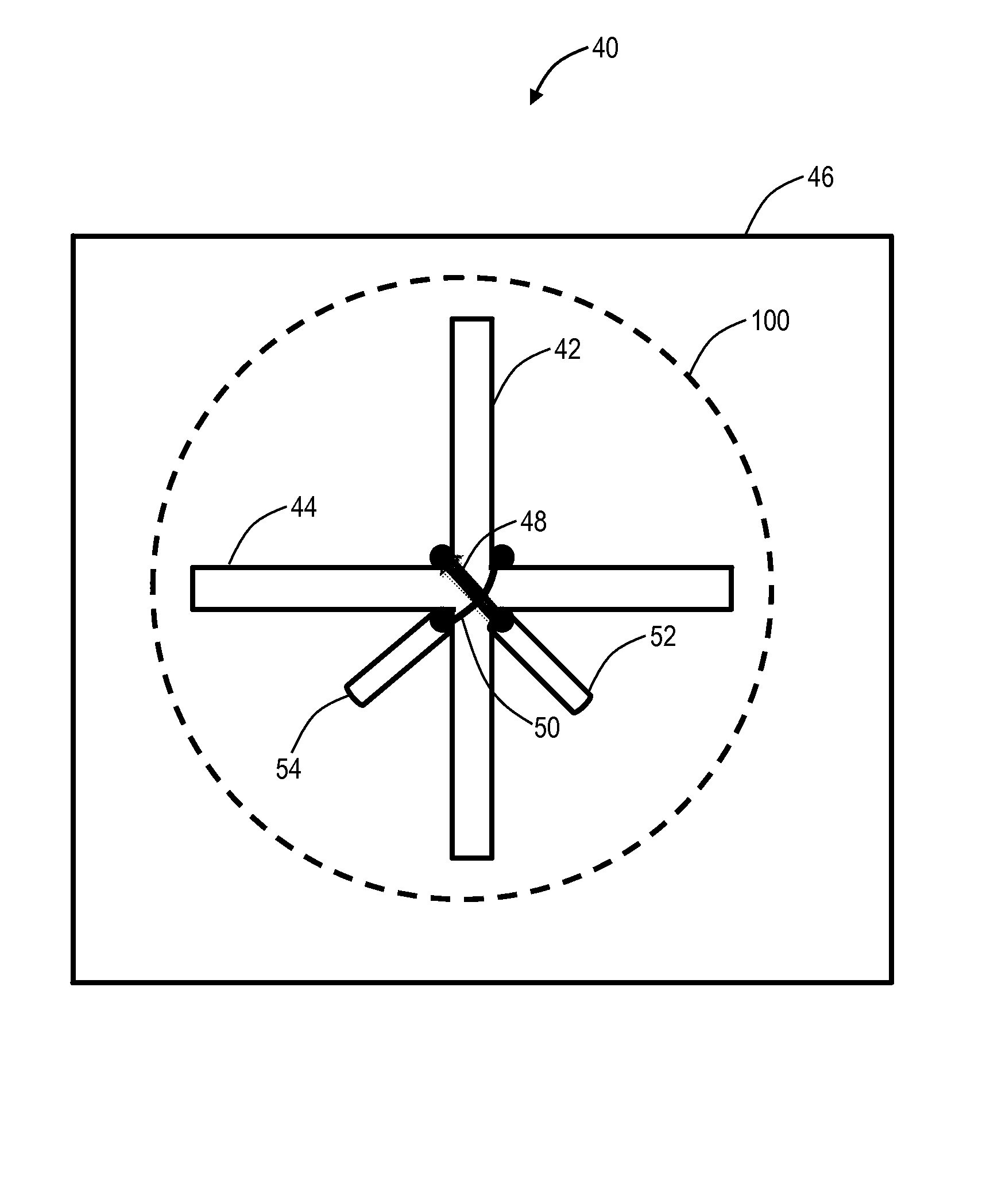
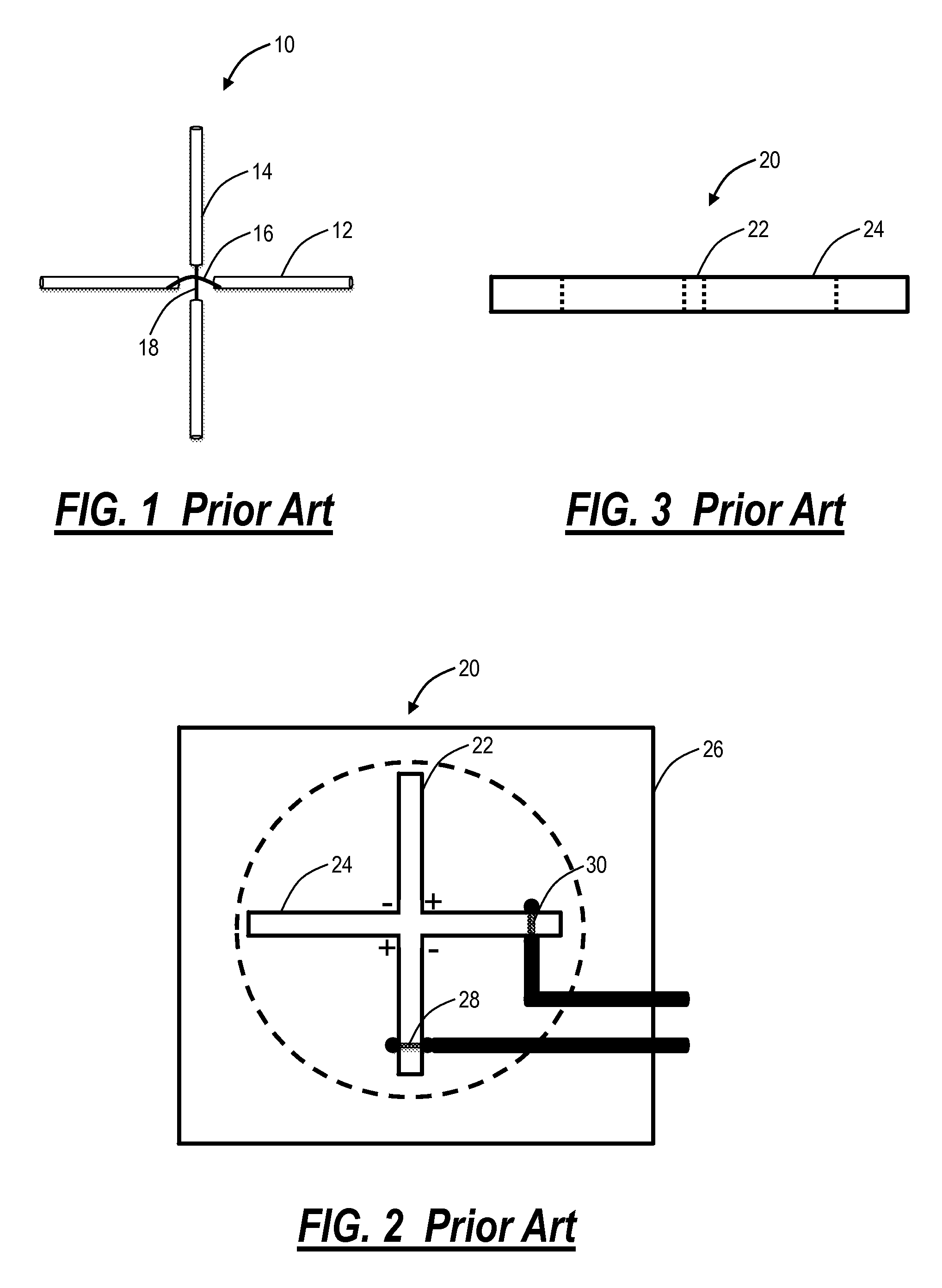
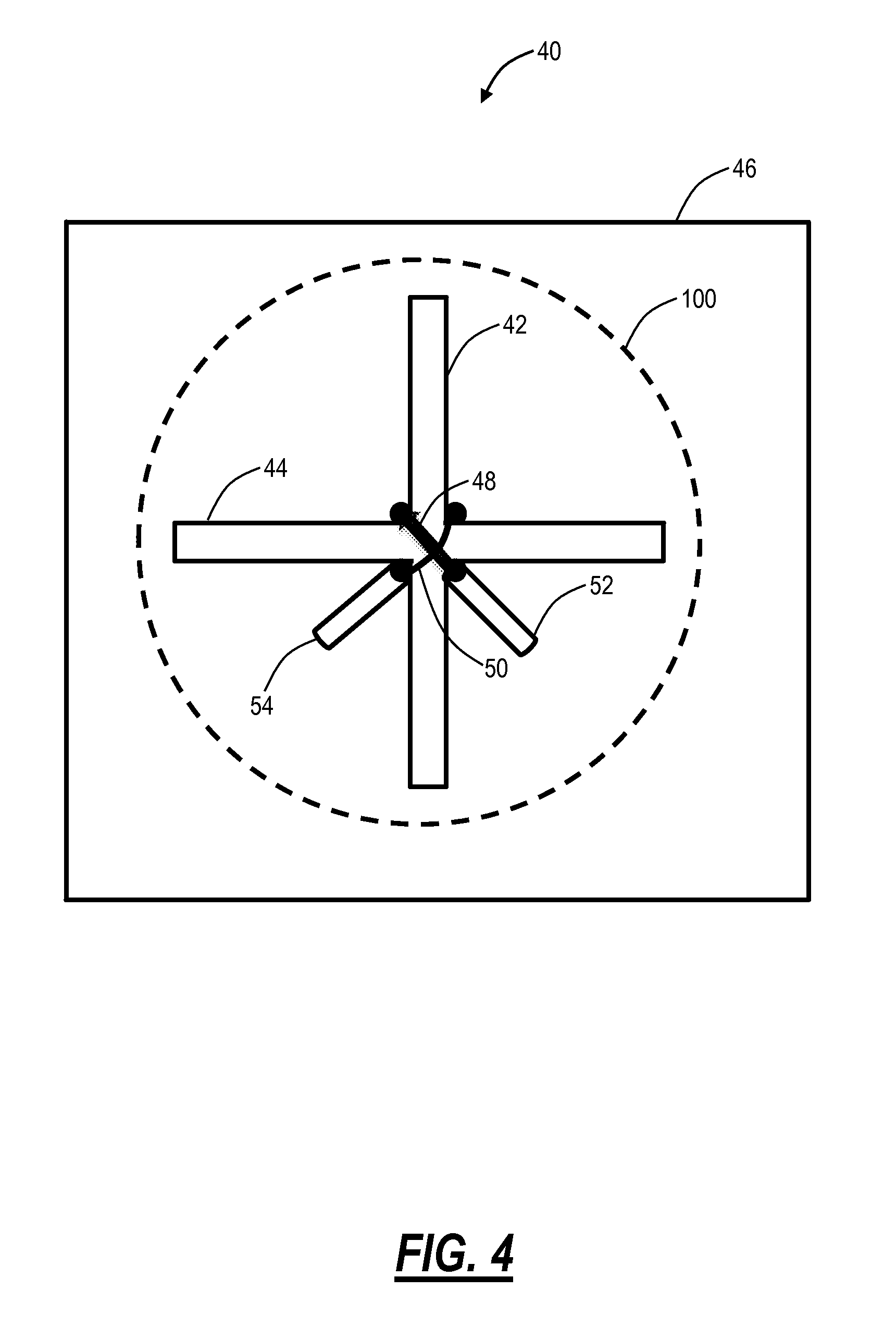
[0012]In various exemplary embodiments, the present disclosure provides a cavity backed cross-slot antenna apparatus and method. In particular, the antenna apparatus and method includes an orthogonal slot antenna which overcomes the aforementioned limitations associated with an RF choke between the adjacent slots. Various feeding techniques are described herein to avoid RF choking when designing overlapping slot antennas for achieving polarization diversity. Variously, the antenna apparatus and method includes a co-located, cross polarized, orthogonal, cavity-backed slot antenna with minimum cross coupling.

[0013]In an exemplary embodiment, a cavity backed cross-slot antenna includes a horizontal slot antenna, a vertical slot antenna sharing a center portion with the horizontal slot antenna, a first feed for the horizontal slot antenna, and a second feed for the vertical slot antenna, the first feed and the second feed provided to the shared center portion. The cavity backed cross-sl...


PUM


Abstract

An antenna apparatus and method includes an orthogonal slot antenna which overcomes the limitations associated with RF choke between the adjacent slots through various feed techniques. A cavity backed cross-slot antenna includes a horizontal slot antenna, a vertical slot antenna sharing a center portion with the horizontal slot antenna, a first feed for the horizontal slot antenna, and a second feed for the vertical slot antenna, the first feed and the second feed provided to the shared center portion. Another cavity backed cross-slot antenna includes a horizontal slot antenna, a vertical slot antenna, the horizontal slot antenna and the vertical slot antenna share a center portion therebetween, a first feed feeding both halves of the horizontal slot antenna, and a second feed feeding both halves of the vertical slot antenna.

Description

FIELD OF THE DISCLOSURE[0001]The present disclosure relates generally to wireless antennas and, more particularly, to a cavity backed cross-slot antenna apparatus and method.BACKGROUND[0002]Polarization diversity between orthogonal polarizations is a key requirement to various antenna applications. For achieving polarization diversity, antennas are often placed orthogonal to each other, which in many balanced antenna designs, rotates the fields by 90 degrees providing true polarization diversity. Some designs take it one step further and overlap antennas (in the min Electric field region) to occupy minimum space and / or volume. One such example is shown in FIG. 1, i.e. an orthogonal dipole arrangement 10. The arrangement 10 includes orthogonal half-wavelength dipole antennas 12, 14 with no corresponding Radio Frequency (RF) choke problems. This is due to the half-wavelength dipole antennas 12, 14 each including balanced feeds 16, 18 at a center portion, i.e. the half-wavelength dipol...

Claims


Application Information

Patent Timeline
Patent Type & Authority Patents(United States)
IPC IPC(8): H01Q13/10
CPCH01Q1/2216H01Q13/18H01Q1/521H01Q21/24
Inventor JAFFRI, REHAN K.KNADLE, RICHARD T.
Owner SYMBOL TECH LLC
Why Eureka
Try Eureka