
Slot fed dipole antenna

a dipole antenna and slot technology, applied in the field of dipole antennas, can solve the problems of unsatisfactory amount of current, significant increase in the overall volume of the antenna, and less flexibility in the implementation of wireless consumer products, so as to reduce the impact of feed cable, improve bandwidth, and reduce current

Inactive Publication Date: 2015-09-03
MOLEX INC
View PDF2 Cites 2 Cited by
  • Summary
  • Abstract
  • Description
  • Claims
  • Application Information

AI Technical Summary

Benefits of technology

The patent describes a new type of antenna that can be used to improve bandwidth and reduce the impact of the feed cable on the antenna system. It uses a low impedance slot fed antenna dipole (LISF-D) that is connected to a coupler that is connected to ground and couples to a radiating element. This design helps reduce the impact of the feed cable on the antenna system and provides improvements in bandwidth compared to conventional dipole antennas.

Problems solved by technology

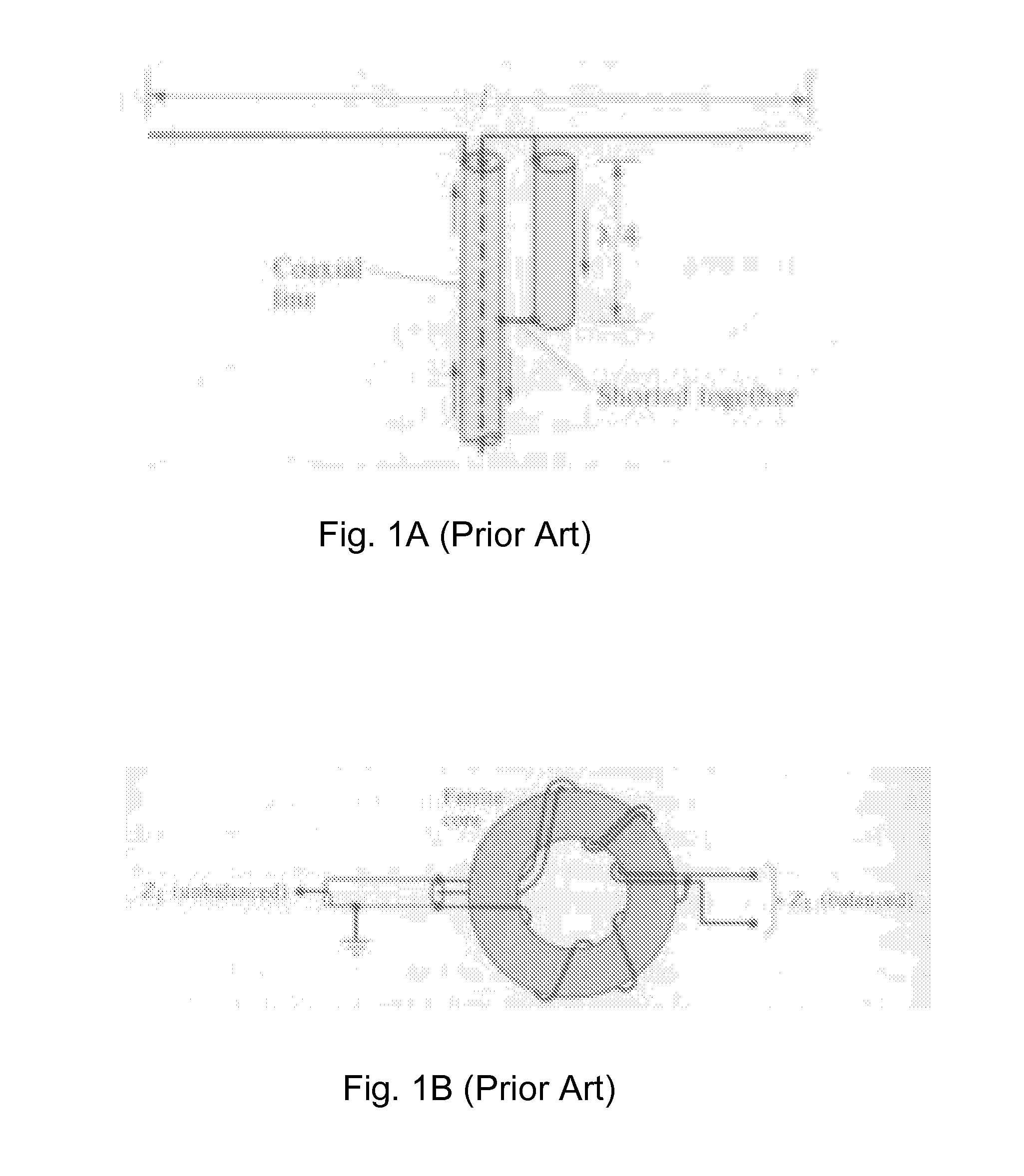
One issue with dipole antennas is that when they are connected to a coax cable there tends to be an undesirable amount of current on the shield of the coax cable.
As can be appreciated, such a configuration results in a significant increase in the overall volume of the antenna.
Therefore, such configurations are less flexible in terms of implementation into wireless consumer products.
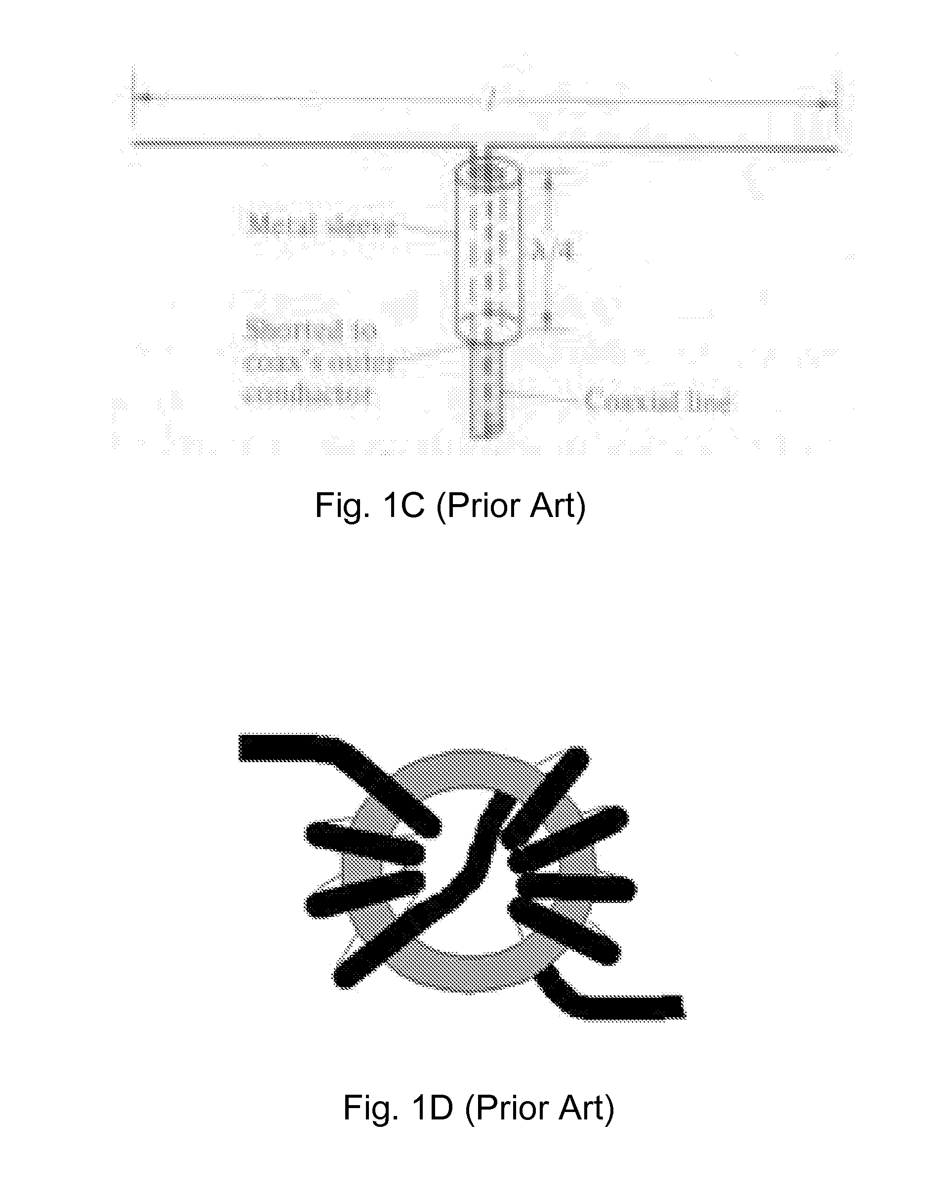
In addition, ferrite core baluns / chokes are lossy and increase the overall cost and size of the antenna.
Due to the relative complicated implementation that would be required, none of the baluns and chokes shown in FIGS. 1A-1D are suited for mass production.

Method used


Image

  • Slot fed dipole antenna
  • Slot fed dipole antenna
  • Slot fed dipole antenna

Examples


Embodiment Construction

[0024]The detailed description that follows describes exemplary embodiments and is not intended to be limited to the expressly disclosed combination(s). Therefore, unless otherwise noted, features disclosed herein may be combined together to form additional combinations that were not otherwise shown for purposes of brevity.

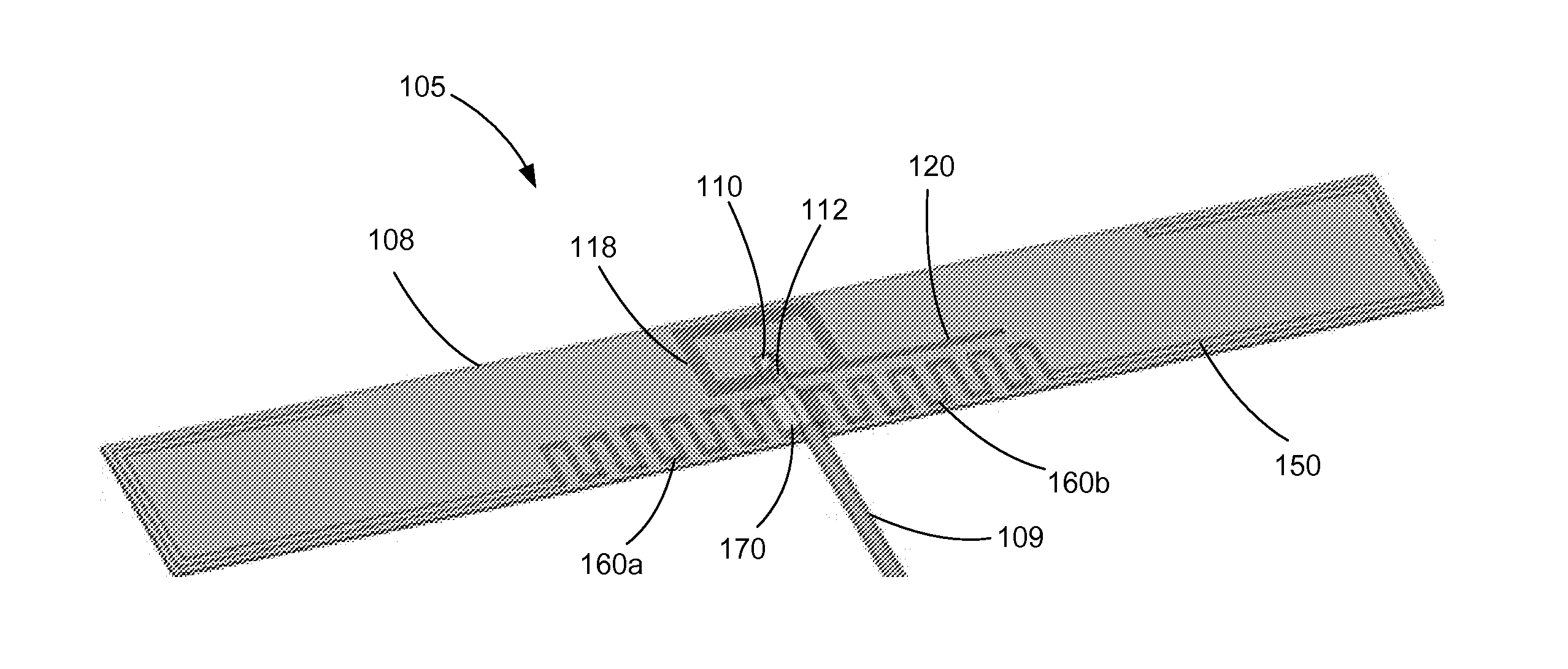
[0025]The following description describes novel techniques for feeding and matching a standard dipole antenna. One potential advantage of the techniques discussed is that the impedance bandwidth can be increased by a factor of more than 2 while that the feed is balanced, so that the effects of the cable can be reduced. Embodiments below include the high impedance slot fed dipole (HISF-D) antennas and a low impedance slot fed dipole (LISF-D), which are naturally balanced structures. The HISF and LISF slot feeding technique increase the impedance bandwidth, without increasing the antenna volume or decreasing the total efficiency.

[0026]It should be noted that when di...


PUM


Abstract

A dipole antenna system is disclosed. An indirect feed technique is used to feed the antenna and the radiating elements are connected to a shield of a coax cable. The balanced termination allows for improved bandwidth compared to conventional dipole antenna configuration and helps manage current on the shield of the coax cable.

Description

RELATED APPLICATIONS[0001]This application claims priority to U.S. Provisional Application No. 61 / 677,680, filed Jul. 31, 2012, which is incorporated herein by reference in its entirety.FIELD OF THE INVENTION[0002]The present invention relates to field of antennas, more specifically to the field of dipole antennas.DESCRIPTION OF RELATED ART[0003]Dipole antennas and their performance are known. In portable device applications, it is common to connect to an antenna with a coax cable, which includes an inner conductor and an outer shield. One issue with dipole antennas is that when they are connected to a coax cable there tends to be an undesirable amount of current on the shield of the coax cable. Baluns and chokes are traditional techniques used to minimize the cable effect on antenna designs. The balun transforms an unbalanced feed into a balanced feed, whereby ideally no currents will flow on the outside of the cable. Chokes increases the impedance on the outside of the coax cable ...

Claims


Application Information

Patent Timeline
Patent Type & Authority Applications(United States)
IPC IPC(8): H01Q9/26H01Q1/48
CPCH01Q1/48H01Q9/26H01Q9/28
Inventor HAUSAGER, FINNJAGIELSKI, OLECHRISTENSEN, MORTENSVENDSEN, SIMON
Owner MOLEX INC
Learn More