Side action insert/skeletal stiffening ribs

a technology of inserts and ribs, which is applied in the field of containers, can solve the problems of spherulitic morphology, interfere with light transmission, and opaque materials, and achieve the effects of improving recyclability, sufficient structural integrity, and improving structural integrity

Active Publication Date: 2014-01-21
AMCOR RIGID PLASICS USA LLC
View PDF10 Cites 9 Cited by
  • Summary
  • Abstract
  • Description
  • Claims
  • Application Information

AI Technical Summary

Benefits of technology

[0004]As a result of environmental and other concerns, plastic containers, more specifically polyester and even more specifically polyethylene terephthalate (PET) containers are now being used more than ever to package numerous commodities previously supplied in glass containers. Manufacturers and fillers, as well as consumers, have recognized that PET containers are lightweight, inexpensive, recyclable and manufacturable in large quantities.
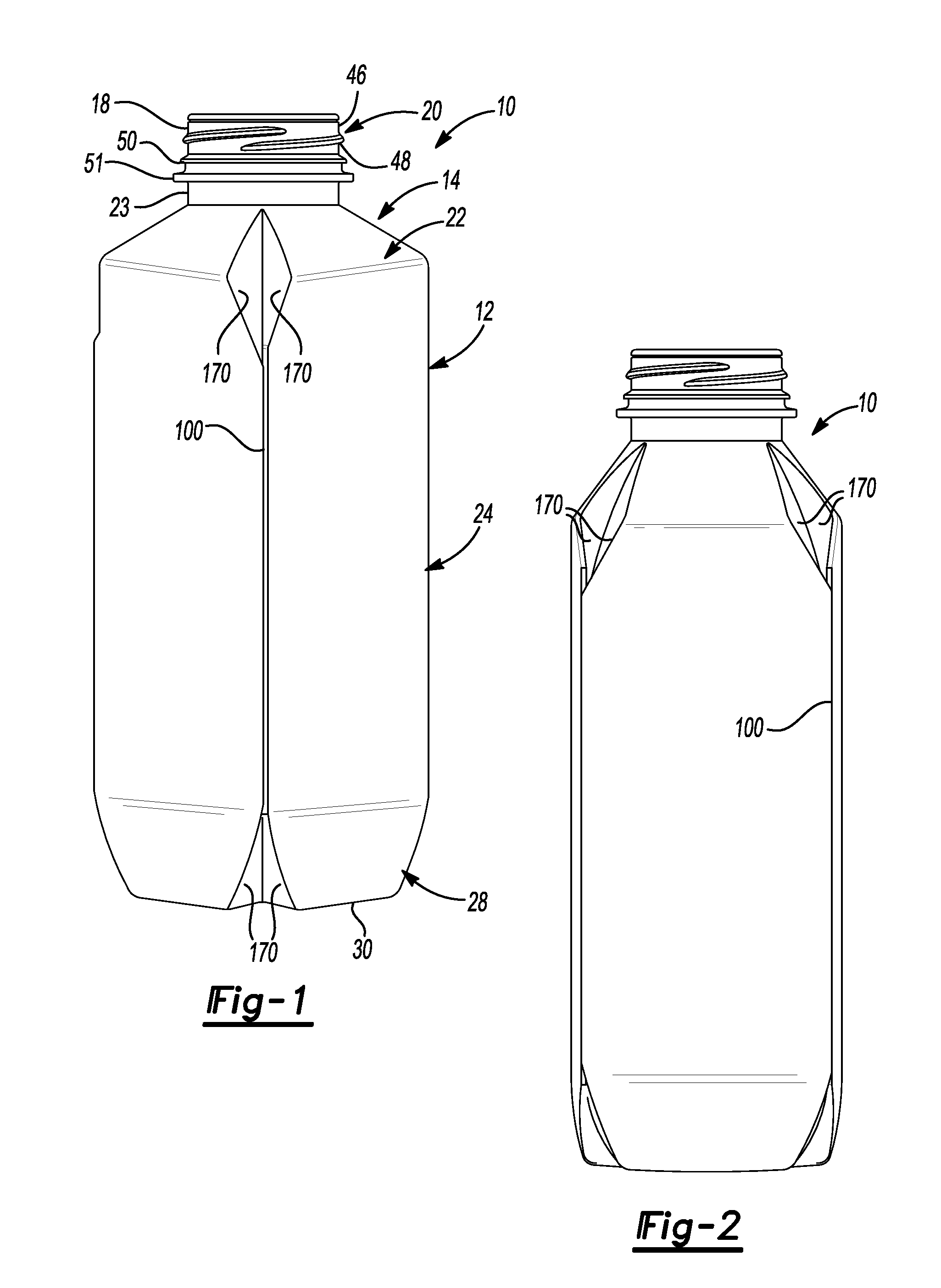
[0026]This disclosure provides for a container being made of PET or other thermoplastic and incorporating one or more vertically oriented reinforcement ribs or seam features. The rib or seam features provide increased structural integrity of the container without unduly increasing its weight or preventing the manufacture, filling, transporting or general use of the container using conventional equipment and processes.
[0030]As shown in FIGS. 1-4, the exemplary plastic container 10 according to the present teachings defines a body 12, and includes an upper portion 14 having a cylindrical sidewall 18 forming a finish 20. Integrally formed with the finish 20 and extending downward therefrom is a shoulder portion 22. The shoulder portion 22 merges into and provides a transition between the finish 20 and a sidewall portion 24. The sidewall portion 24 extends downward from the shoulder portion 22 to a base portion 28 having a base 30. In some embodiments, sidewall portion 24 can extend down and nearly abut base 30, thereby minimizing the overall area of base portion 28 such that there is not a discernable base portion 28 when exemplary container 10 is uprightly-placed on a surface.
[0035]Alternatively, in some embodiments, flash can be used to create or define the reinforcing ribs and seams 100. That is, a parting line between portions of the mold can be positioned such that material that flows within this mold seams results in a narrow rib of material along the outside surface of sidewall portion 24. In this way, the narrow rib of material forms a structural reinforcing member that is provides improved structural integrity of container 10. In some embodiments, this flash material can be trimmed to a desired size and or shape; however, it should be appreciated that this is an optional processing step. In some embodiments, these principles can be combined with optional standing ring features to provide additional benefits and advantages.
[0036]In some embodiments, the principles of the present teachings can be used to manufacture stand-up-pouch-like structures that include the consumer benefits of PET bottles and improved recyclability as compared to current stand-up-pouch offerings. Additionally, the principles of the present teachings provide sufficient structural integrity to enable the container to survive existing storage, distribution, and filling infrastructure.
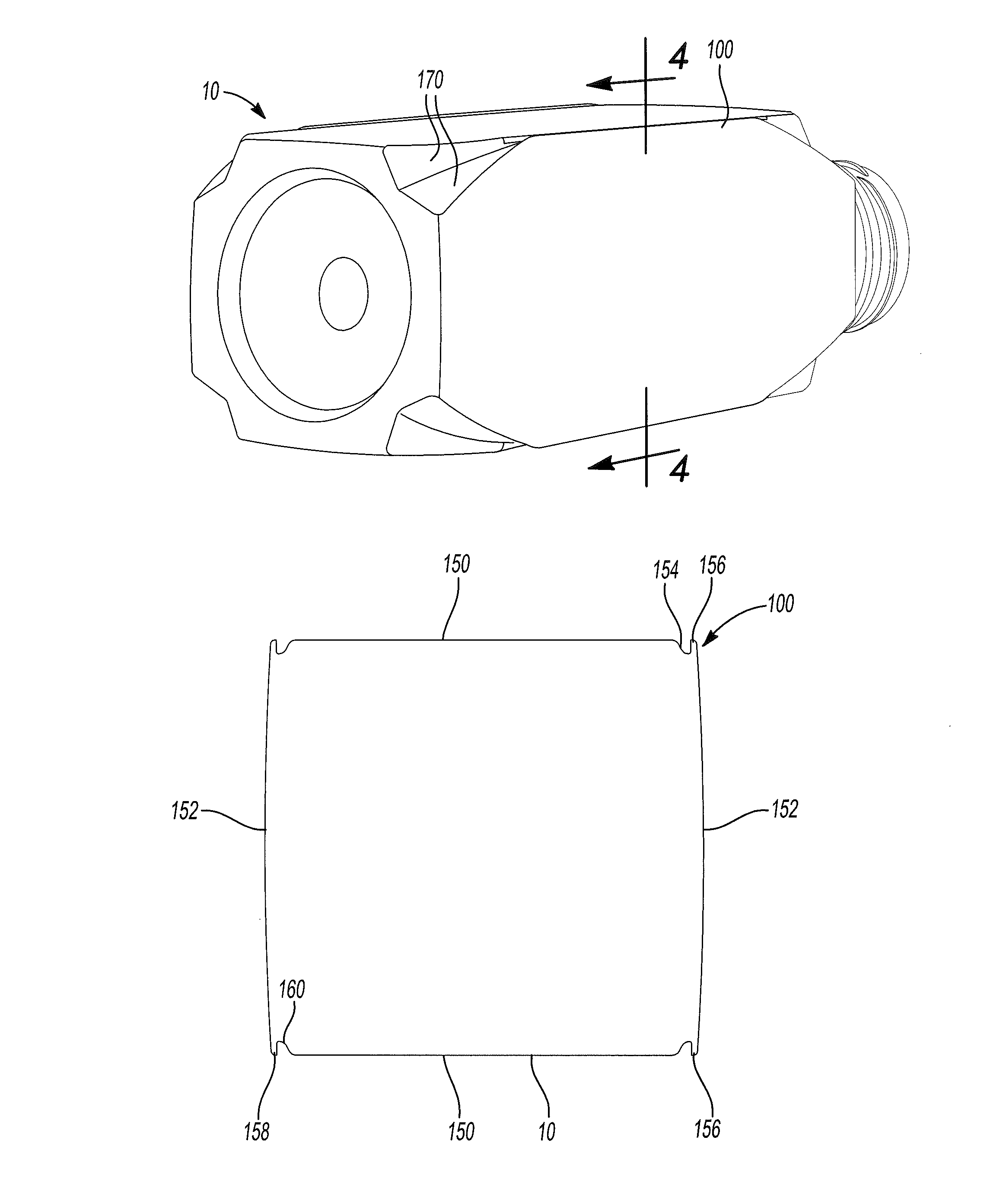
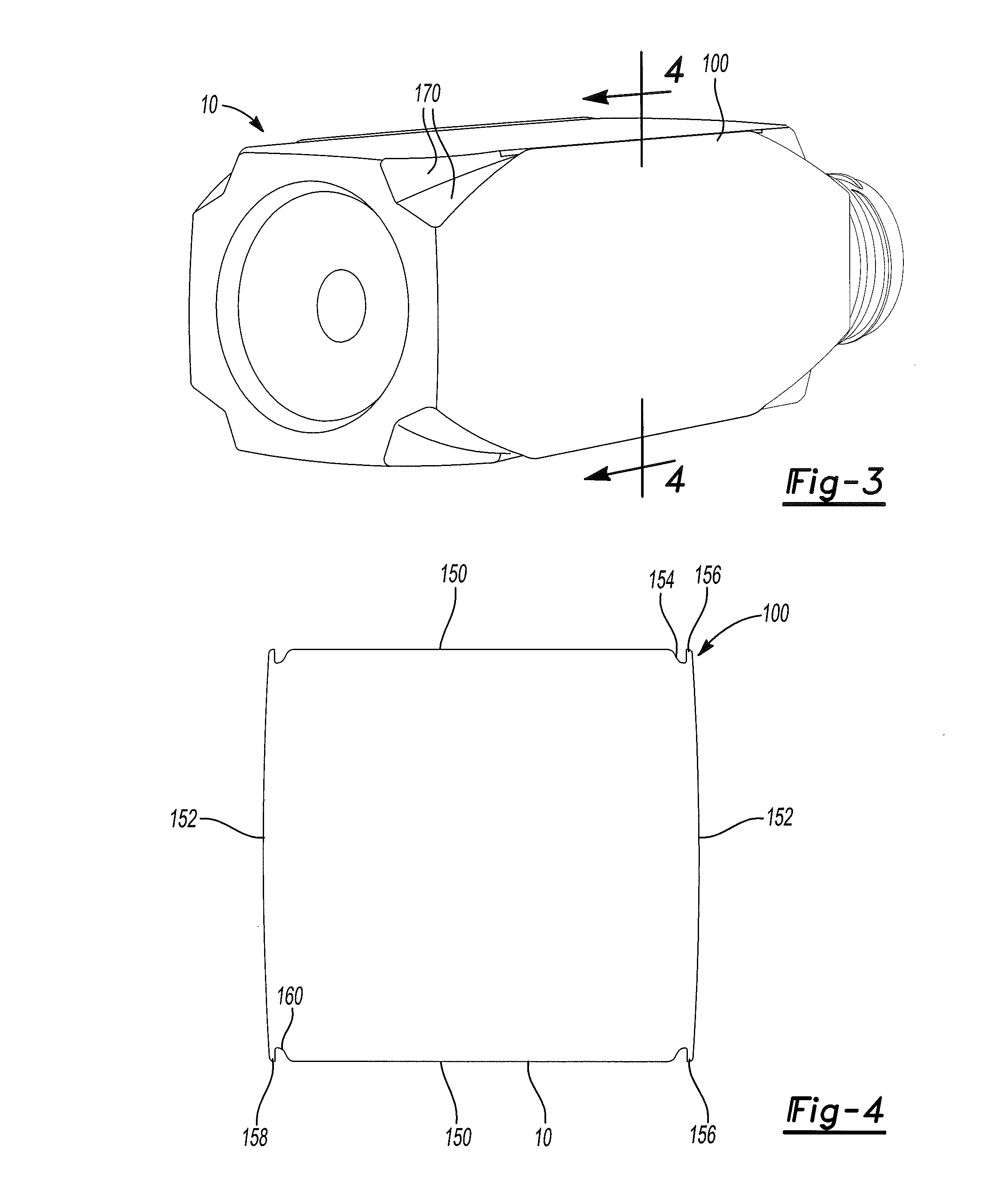
[0037]In some embodiments, as illustrated in FIG. 4, reinforcing ribs or seams 100 can be formed at corner portions 110 of sidewall portion 24. Specifically, in some embodiments, reinforcing ribs or seams 100 can be formed such that they are viewable from alternating sides of container 10. That is, ribs or seams 100 can be viewable from sides 150, while generally concealed from sides 152. As such, ribs or seams 100 can define an inwardly directed channel 154 resulting in an outwardly directed portion 156. In some embodiments, outwardly directly portion 156 can be shaped similar to a finger having a distal tip 158. In some embodiments, as shown, distal tip 158 of outwardly directed portion 156 of reinforcing rib or seam 100 can extend along side 152 to a position generally even with adjacent side 150. This can permit labels to smoothly conform to the outermost shape of the container 10 and / or provide an unobstructive container contour that is generally pleasing to the touch. However, it should be recognized that distal tip 158 can extend along side 152 to a position beyond adjacent side 150 and / or to a position below adjacent side 150.

Problems solved by technology

On amorphous material, thermal processing of PET material results in a spherulitic morphology that interferes with the transmission of light.
In other words, the resulting crystalline material is opaque, and thus, generally undesirable.
Unfortunately, in some applications, containers are often exposed to a wide variety of manufacturing, filling, transporting, and using forces that vary greatly.
Consequently, however, any major revisions of these containers can lead to the need for revised manufacturing and transportation solutions, which can quickly consume any savings realized through container redesign and reconstruction.

Method used


Image

  • Side action insert/skeletal stiffening ribs
  • Side action insert/skeletal stiffening ribs
  • Side action insert/skeletal stiffening ribs

Examples


Embodiment Construction

[0021]Example embodiments will now be described more fully with reference to the accompanying drawings. Example embodiments are provided so that this disclosure will be thorough, and will fully convey the scope to those who are skilled in the art. Numerous specific details are set forth such as examples of specific components, devices, and methods, to provide a thorough understanding of embodiments of the present disclosure. It will be apparent to those skilled in the art that specific details need not be employed, that example embodiments may be embodied in many different forms and that neither should be construed to limit the scope of the disclosure.

[0022]The terminology used herein is for the purpose of describing particular example embodiments only and is not intended to be limiting. As used herein, the singular forms “a”, “an” and “the” may be intended to include the plural forms as well, unless the context clearly indicates otherwise. The terms “comprises,”“comprising,”“includ...


PUM


Abstract

A container comprising a finish, a sidewall portion extending from the finish, a base portion extending from the sidewall portion and enclosing the sidewall portion to form a volume therein for retaining a commodity, and an outwardly directed rib member.

Description

CROSS-REFERENCE TO RELATED APPLICATIONS[0001]This application claims the benefit of U.S. Provisional Application No. 61 / 365,865, filed on Jul. 20, 2010. The entire disclosure of the above application is incorporated herein by reference.FIELD[0002]This disclosure generally relates to containers for retaining a commodity, such as a solid or liquid commodity. More specifically, this disclosure relates to a container having vertically disposed stiffening ribs extending along at least a sidewall of a container.BACKGROUND AND SUMMARY[0003]This section provides background information related to the present disclosure which is not necessarily prior art. This section also provides a general summary of the disclosure, and is not a comprehensive disclosure of its full scope or all of its features.[0004]As a result of environmental and other concerns, plastic containers, more specifically polyester and even more specifically polyethylene terephthalate (PET) containers are now being used more th...

Claims


Application Information

Patent Timeline
Patent Type & Authority Patents(United States)
IPC IPC(8): B65D90/02B65D6/38
CPCB65D2501/0081B65D1/0223B65D1/42B65D2501/0027
Inventor LANE, MICHAEL T.WILSON, BRAD
Owner AMCOR RIGID PLASICS USA LLC
Why Eureka
Try Eureka