LED and fiber optic ring pathway light

a fiber optic and pathway light technology, applied in the field of pathways and landscape lights, can solve the problems of low light emission, different levels of light emission, and undesirable shadow spot effects on the ends of each surface, and achieve the effect of removing undesirable shadow effects

Active Publication Date: 2014-01-21
CHIEN LUEN INDS
View PDF19 Cites 24 Cited by
  • Summary
  • Abstract
  • Description
  • Claims
  • Application Information

AI Technical Summary

Benefits of technology

[0010]A primary objective of the present invention is to provide devices, apparatus, systems and methods of using ground directed pathway and landscape lights with perimeter spaced apart LED (light emitting diode) light sources that eliminate undesirable shadow effects from cluster based light sources.

Problems solved by technology

However, a single LED is still known to emit low levels of light which are impractical for providing sufficient light for gardens and walkways.
However, there are additional problems with the cluster based prior art. FIG. 1 shows a side view of a traditional ground based pathway / landscape light 1 with light source 20 including a centrally located cluster of closely spaced LEDS.
Users have complained about the undesirable shadow spot effects on the ends of each of the surface striking light beams that are emitted from the cluster based landscape lights.
Additionally, users have complained about the light emissions having different levels of illumination on the ground with parts of the light beams. FIG. 2 shows the illumination effects create different levels of brightness on the surface being illuminated.
Some of the light emissions are extremely bright and harsh while other parts of the light emissions are very dim.
As a result of the dark spots and different levels of illumination of brightness, a ground surface may not be adequately illuminated so that walkers using the path will not have enough light to see obstructions in the path.
None of the known prior art uses LEDs to direct light in beneath a dome lens covered pathway and landscape light source, where the light is intended to be emitted in a 360 degree direction from the pathway / landscape light.
None of the prior art would solve the problem of eliminating shadow effects and different levels of brightness in the light emissions being generated therefrom.

Method used


Image

  • LED and fiber optic ring pathway light
  • LED and fiber optic ring pathway light
  • LED and fiber optic ring pathway light

Examples


first embodiment

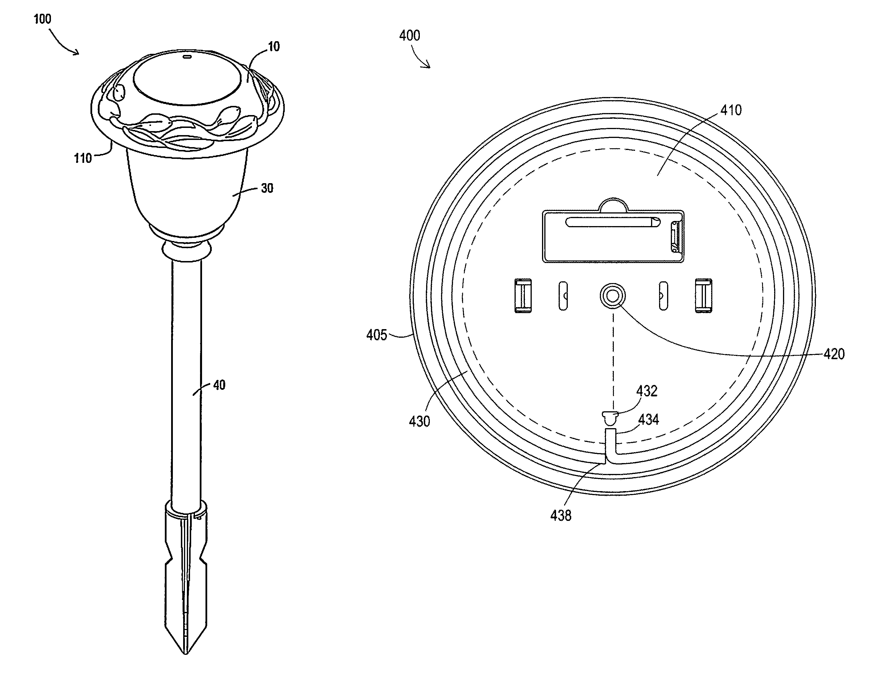
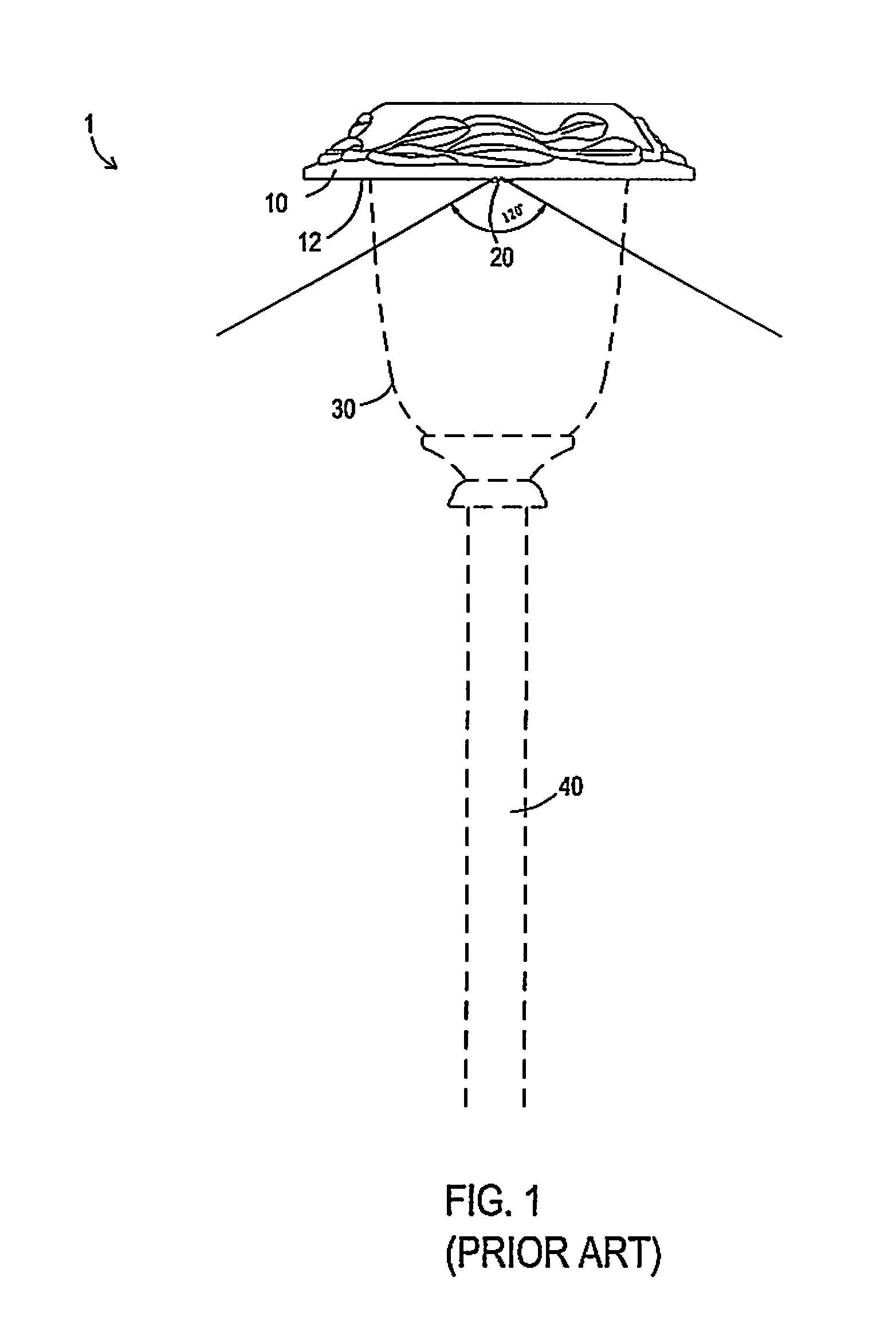
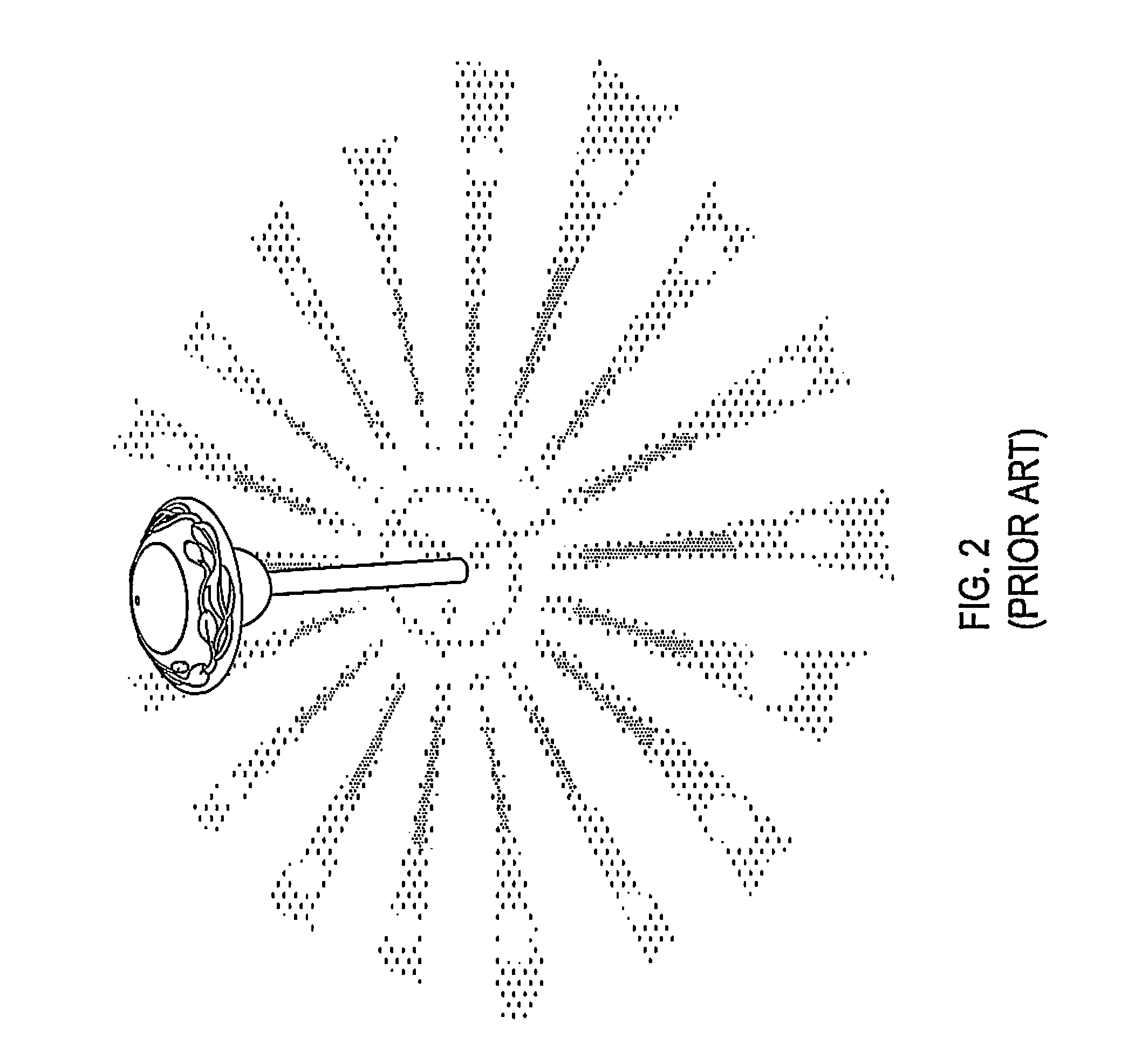
[0052]1. prior art version of pathway light[0053]10. cover of pathway light[0054]12. bottom facing mount surface[0055]20. centrally located cluster of LEDs[0056]30. light shade lens[0057]40. ground engaging post[0058]100. first embodiment of plurality of perimeter configured LEDS[0059]110. bottom surface of mount[0060]120. plurality of perimeter attached LEDs.[0061]122. first LED[0062]124. second LED[0063]126. third LED[0064]129. centrally located LED[0065]200. square and rectangular arrangement of LEDs[0066]210. bottom surface of the mount[0067]300. hexagon arrangement of LEDs[0068]310. bottom surface of the mount[0069]400. Optical Fiber Ring about single or plural LEDS[0070]405. lower hanging perimeter edge of light cover[0071]410. bottom surface of mount[0072]420. centrally located LED[0073]430. optical fiber in ring configuration.[0074]432. input for optical fiber[0075]434. input end of optical fiber[0076]438. outer end of optical fiber[0077]440. light shade lens[0078]442. base ...

embodiment 100

[0085]An additional version of the embodiment 100 can include a centrally located single LED 129 in the disc shaped mount surface 110, where the central LED 129 is located equally distant from the other LEDs 122, 124, 126.

[0086]FIG. 7 is a side view of the novel light 100 showing the direction of beams emitting from the perimeter located LEDs 122, 124 (126 is not shown) and centrally located LED 129. FIG. 8 shows light emissions on a ground surface using the novel pathway / landscape light of FIGS. 3-7. As shown in FIGS. 7-8, the light beams striking a ground surface do not have the dark spots and effects that exist with the prior art. With the invention, the emitted light beams have a generally uniform brightness throughout each of the beams creating a more aesthetic and desirable effect, as well as more thoroughly illuminate an entire ground surface in 360 degrees than the prior art.

embodiment 200

[0087]FIG. 9 is a bottom view of another embodiment 200 of a rectangular configuration of LEDs. In this embodiment 200, there can be 4 LEDS each located about all 4 corners of a square configuration. An additional central located LED can be optionally located in a mid portion of the mount surface 210. Each the 4 LEDs can be located between approximately 3 inches to approximately 5 inches apart from one another, where the LEDs are equally spaced apart from one another. Additional LEDs can be located on each leg of the square between each of the corner located LEDs.


PUM


Abstract

Pathway and landscape lights, in particular to devices, apparatus, systems and methods of using ground directed pathway and landscape lights with a single or perimeter spaced apart LED (light emitting diode) light sources on a disc mount, with or without an optical fiber arranged in a ring pattern about a perimeter edge of the mount. A light shade lens can have an upper end attached to the lower face of the disc mount, and a bottom end attached to a ground engaging post, so the light emitted from the mount is directed in a 360 degree outwardly expanding direction expanding outward on the ground surface where the ground engaging post is in the center of the 360 degree expanding illumination. A low voltage power source can be used. Alternatively, the light can be solar powered. The light forms uniform light beam emissions without shadow spots effects.

Description

[0001]This invention is a Continuation-In-Part of U.S. patent application Ser. No. 13 / 229,307 filed Sep. 9, 2011, the entire disclosure of which is incorporated by reference in its' entirety.FIELD OF INVENTION[0002]This invention relates to pathway and landscape lights, in particular to devices, apparatus, systems and methods of using ground directed pathway and landscape lights with a ring configured optical fiber which directs light emissions from a centrally located LED (light emitting diode) light source.BACKGROUND AND PRIOR ART[0003]Pathway and landscape lighting are known for providing light sources for gardens, walkways, and the like. LEDS (light emitting diodes) have become increasingly popular over the years as a light source since the LEDs have become more cost effective as well as provide for low power consumption and longer life over standard light bulbs, and the like. However, a single LED is still known to emit low levels of light which are impractical for providing su...

Claims


Application Information

Patent Timeline
Patent Type & Authority Patents(United States)
IPC IPC(8): F21V7/04
CPCF21S4/00F21S8/081
Inventor LOWE, TIEN S.VELUTINI, MARKRIVERA, ELI E.ZHOU, JOEBIANCUZZO, FRANCISCO
Owner CHIEN LUEN INDS
Why Eureka
Try Eureka