LED (Light-Emitting Diode) energy-saving lamp

A technology of LED energy-saving lamps and LED light sources, applied in the cooling/heating devices of lighting devices, lighting and heating equipment, point light sources, etc., can solve the problem of poor heat dissipation effect, shortened life, glass fiber board and adhesive Sexual problems, etc.

Inactive Publication Date: 2013-01-02
中山市古镇臻霖五金厂
View PDF0 Cites 2 Cited by
  • Summary
  • Abstract
  • Description
  • Claims
  • Application Information

AI Technical Summary

Problems solved by technology

At present, the illuminants of almost all corncob-shaped LED energy-saving lamps on the market include a cylinder, a glass fiber board installed and fixed on the side of the cylinder, and an LED light source arranged on the glass fiber board. It is made of plastic with poor thermal conductivity, and the glass fiber board is generally fixed on the plastic cylinder by an adhesive. The thermal conductivity of the glass fiber board and the adhesive is poor, and the heat generated by the LED light source is difficult to dissipate from the glass fiber board or The plastic cylinder is passed out, and the heat dissipation effect is poor
In addition, the luminous body of some LED energy-saving lamps is equipped with a light-transmitting cover to prevent water splashing and leakage, but this design makes the luminous body in a sealed state, and the heat generated by the LED light source cannot be dissipated to the outside of the lamp. Working in a confined space, long-term heat accumulation will have a greater impact on the chip of the LED light source, which will eventually cause serious light decay and shorten the life of the LED light source

Method used


Image

  • LED (Light-Emitting Diode) energy-saving lamp
  • LED (Light-Emitting Diode) energy-saving lamp
  • LED (Light-Emitting Diode) energy-saving lamp

Examples


Embodiment Construction

[0025] It should be understood that the specific embodiments described here are only used to explain the present invention, not to limit the present invention.

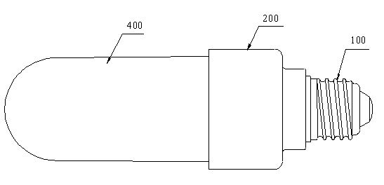
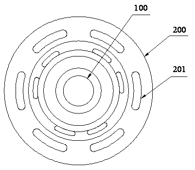
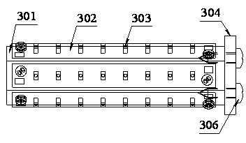
[0026] refer to Figure 1 to Figure 8 , an embodiment of an LED energy-saving lamp according to the present invention is proposed. The lamp cap 100, the lamp holder 200, and the luminous body are sequentially connected and fixed from top to bottom. drive unit. The illuminant includes a thermally conductive metal cylinder 301 , an aluminum substrate 302 on which LED light sources 303 are uniformly distributed, and a fixing plate 304 for mounting the metal cylinder 301 on the lamp holder 200 . The circuit board adopts the aluminum substrate 302 with better thermal conductivity than the glass fiber board, the heat can be transferred from the LED light source 303 to the aluminum substrate 302 in time and quickly, and the heat on the aluminum substrate 302 can be quickly transferred to the metal cylinder 301. The cross s...


PUM


Abstract

The invention discloses an LED (Light-Emitting Diode) energy-saving lamp, which is formed by connecting a lamp head, a lamp holder and a light-emitting body from top to bottom. The light-emitting body comprises a metal column body which has heat conduction and is provided with a polygonal section, an aluminum substrate distributed with an LED light source, and a fixing plate for mounting the metal column body on the lamp holder; the aluminum substrate is in a long strip shape and is adapted with the shape of any outer side face of the metal column body; two ends of the aluminum substrate are fastened on the outer side face of the metal column body through a screwing manner; the metal column body is fixedly arranged on the fixing plate through the screwing manner; the metal column body is in a hollow structure; the fixing plate is provided with an air ventilating hole and the lamp holder is integrally provided with a heat radiation through hole; and the hollow structure, the air ventilating hole and the heat radiation through hole are communicated. The column body is made of heat-conducting metal; the aluminum substrate and the metal column body are fixed through the screwing manner, and the metal column body and the fixing plate are fixed through the screwing manner, so that the heat is rapidly transmitted to the whole metal column body and the fixing plate. The hollow structure, the air ventilating hole and the heat radiation through hole are communicated with one another, so that the heat can be radiated in time through the flowing of the air.

Description

technical field [0001] The invention relates to an LED lighting fixture, in particular to an LED energy-saving lamp. Background technique [0002] LED energy-saving lamp is a kind of LED lamp, because the maximum luminous angle of LED is 120 degrees, considering the uniformity of light emission, it is specially designed to emit light at 360 degrees, and its shape is like a corn cob, so such LED energy-saving lamps are sometimes called LED corn lamp. Compared with traditional light sources, LED energy-saving lamps are widely used because of their good light efficiency, energy saving and environmental protection, long life, and small size. LED energy-saving lamps are suitable for all indoor lighting fields such as homes, hotels, schools, and hospitals. At present, the illuminants of almost all corncob-shaped LED energy-saving lamps on the market include a cylinder, a glass fiber board installed and fixed on the side of the cylinder, and an LED light source arranged on the gla...

Claims


Application Information

Patent Timeline
Patent Type & Authority Applications(China)
IPC IPC(8): F21S2/00F21V29/00F21V17/12F21V5/00F21Y101/02F21V29/77F21V29/83F21V29/89
Inventor 林根权雷雨周克佳
Owner 中山市古镇臻霖五金厂
Why Eureka
Try Eureka