Cylindrical LED lamp capable of emitting light uniformly

A technology of LED lighting and LED light source, applied in lighting devices, lighting and heating equipment, light guides of lighting systems, etc., can solve problems such as difficulty in obtaining lighting distribution, single irradiation direction, and difficulty in meeting indoor lighting requirements.

Inactive Publication Date: 2012-10-31
DUJIANGYAN HUAGANG ELECTRONICS TECH
View PDF1 Cites 2 Cited by
  • Summary
  • Abstract
  • Description
  • Claims
  • Application Information

AI Technical Summary

Problems solved by technology

However, in the common design, the light-emitting diode module of the lamp is generally placed on one surface of an integrally formed bulky substrate to form a single planar light source. The substrate is usually a high thermal conductivity with heat dissipation function This type of planar light source has a single irradiation direction and a limited irradiation area, making it difficult to obtain an ideal lighting distribution, let alone form a uniform and soft lighting around the lamp, which seriously restricts the popularization and application of LED lighting, especially difficult to meet The application requirements of indoor lighting, in response to this requirement, Chinese patent document CN101713524A discloses an LED indoor lamp, including a frame, a number of LED modules arranged on the frame, a light guide cover arranged on the LED module, and a The power circuit module on the frame is characterized in that: the frame includes a plurality of conical tubes sleeved at intervals, the LED module is arranged on the outer surface of each conical tube, and the inner ring of the conical tube is placed on the At least part of the light emitted by the LED module is irradiated outside the projection area of ​​the outer conical tube in the light emitting direction. The LED indoor lamp with this structure has a m

Method used


Image

  • Cylindrical LED lamp capable of emitting light uniformly
  • Cylindrical LED lamp capable of emitting light uniformly

Examples


Embodiment Construction

[0018] The present invention will be further elaborated below in conjunction with the accompanying drawings, and the legends used are schematic and should not be regarded as limitations on any features such as proportions or shapes.

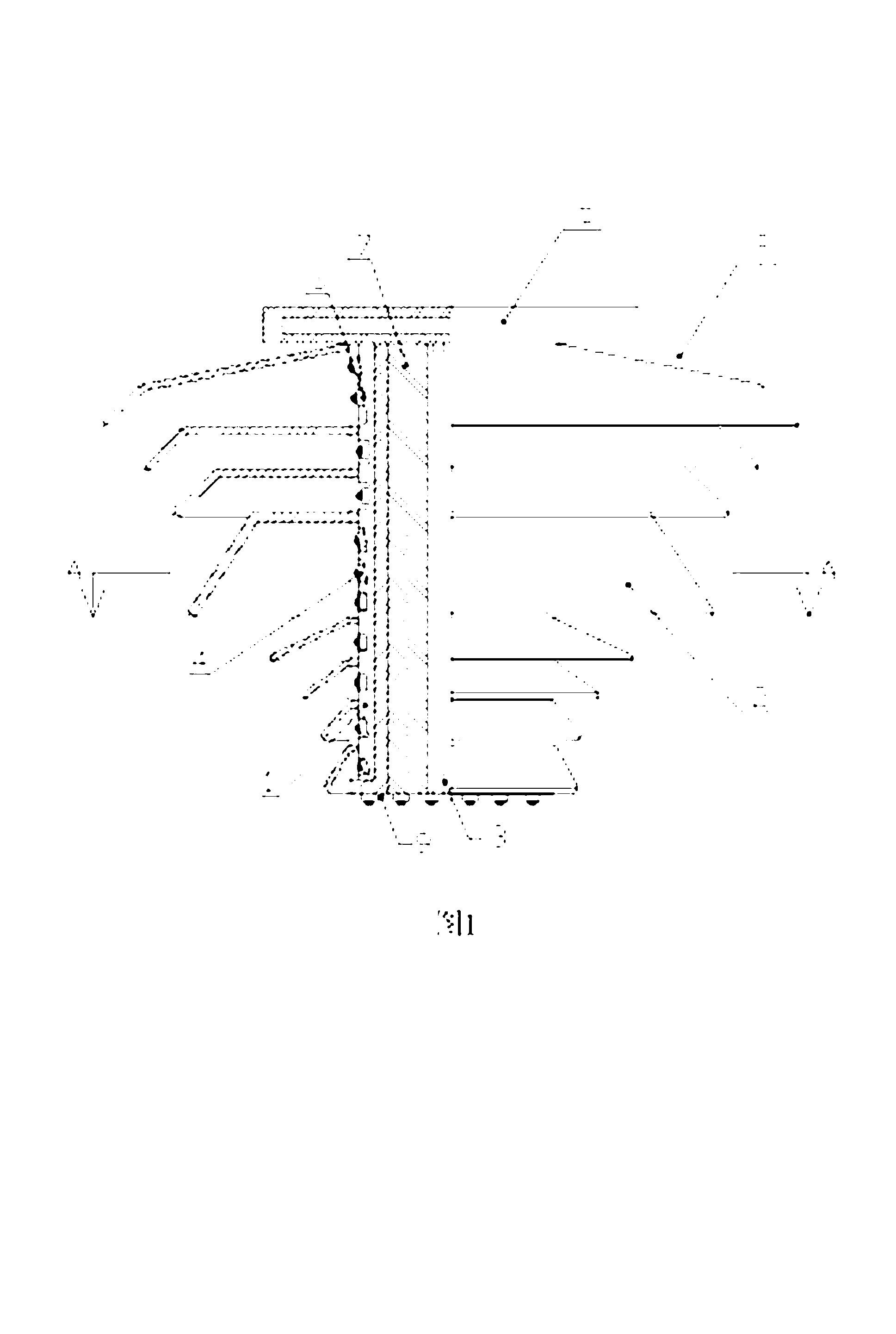
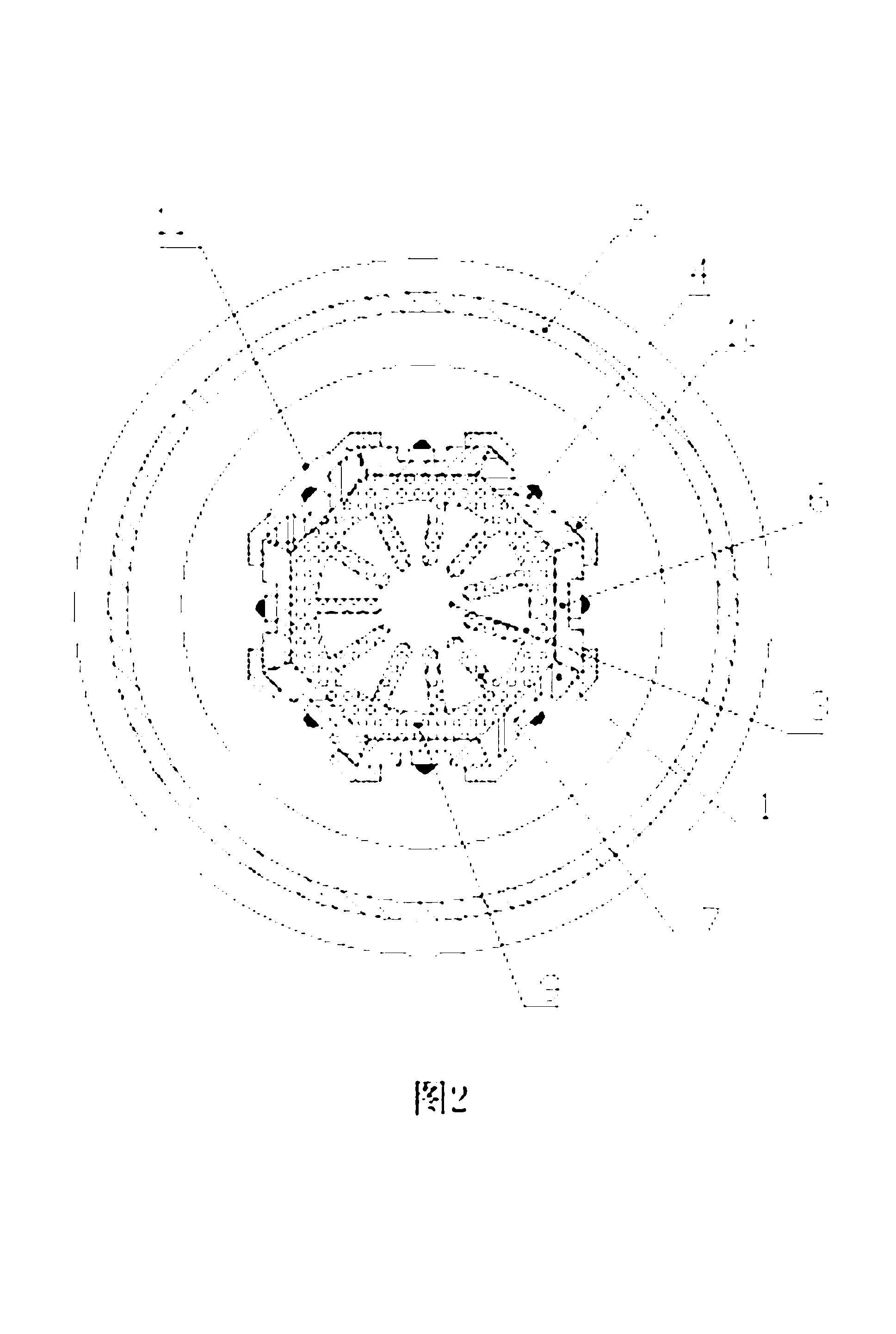
[0019] like figure 1 and figure 2 As shown, the cylindrical uniform light LED lighting includes: an LED light source consisting of eight LED modules 11, a radiator 9 formed with cooling fins 7, and a light guide cover 8 composed of eight conical tubes 2. , and the power circuit module 5,

[0020] The radiator 9 is cylindrical, and the outer cylindrical surface is symmetrically provided with eight LED light source installation surfaces, and the two sides of each LED light source installation surface are vertically provided with locking strips 10, which form chutes opposite each other. The core position of 9 is penetrated with a heat dissipation cavity 3. The LED module 11 is composed of a strip-shaped aluminum substrate 1 and LED lamp beads 4 f...


PUM


Abstract

The invention discloses a cylindrical LED lamp capable of emitting light uniformly. The cylindrical LED lamp capable of emitting light uniformly comprises an LED light source, a cylindrical radiator (9), a light diffuser (8) and a power circuit module (5). An LED light source mounting surface is formed on the outer cylindrical surface of the radiator (9), and a radiating through-cavity (3) is formed in the core of the cylindrical radiator (9). The light diffuser comprises a plurality of cone-like barrels (2), and reflecting layers are formed on the upper surfaces and/or the lower surfaces of the cone-like barrels (2). An LED light source is mounted on the radiator (9) to form a cylindrical lamp core, and the cone-like barrels (2) are sleeved on the cylindrical lamp core layer by layer at intervals, so that at least part of light rays, reflected by the cone-like barrels on the upper layer, emitted from the LED light source, are irradiated outside a radiating region, reflected by the cone-like barrels on the lower layer, of the LED light source. The cylindrical LED lamp capable of emitting light uniformly has wide irradiation area and soft and uniform light rays, and is more convenient to assemble and maintain.

Description

[0001] technical field [0002] The invention relates to an illuminating device, in particular to an LED illuminating lamp with a uniform light output and a columnar structure. [0003] Background technique [0004] As a new light source, LED (Light Emitting Diode) light source is favored in many fields due to its advantages of safety, energy saving, long life and environmental protection. With the continuous development and maturity of LED light source, LED modules have been able to produce sufficient brightness Light will surely replace existing light sources such as incandescent lamps revolutionaryly. However, in the common design, the light-emitting diode module of the lamp is generally placed on one surface of an integrally formed bulky substrate to form a single planar light source. The substrate is usually a high thermal conductivity with heat dissipation function This type of planar light source has a single irradiation direction and a limited irradiation area, mak...

Claims


Application Information

Patent Timeline
IPC IPC(8): F21S2/00F21V29/00F21V8/00F21V7/22F21V19/00F21Y101/02F21V29/503F21V29/77
Inventor 陈刚
Owner DUJIANGYAN HUAGANG ELECTRONICS TECH
Why Eureka
Try Eureka