

Dimmable light source with light temperature shift
a technology of dimming light and dimming light, which is applied in the direction of electric variable regulation, process and machine control, instruments, etc., can solve the problems of relatively high cost of driver circuits and dimming of illumination devices, and achieve the effect of simple and cost-efficien
- Summary
- Abstract
- Description
- Claims
- Application Information
AI Technical Summary
Benefits of technology
Problems solved by technology
Method used
Image

Examples
Embodiment Construction
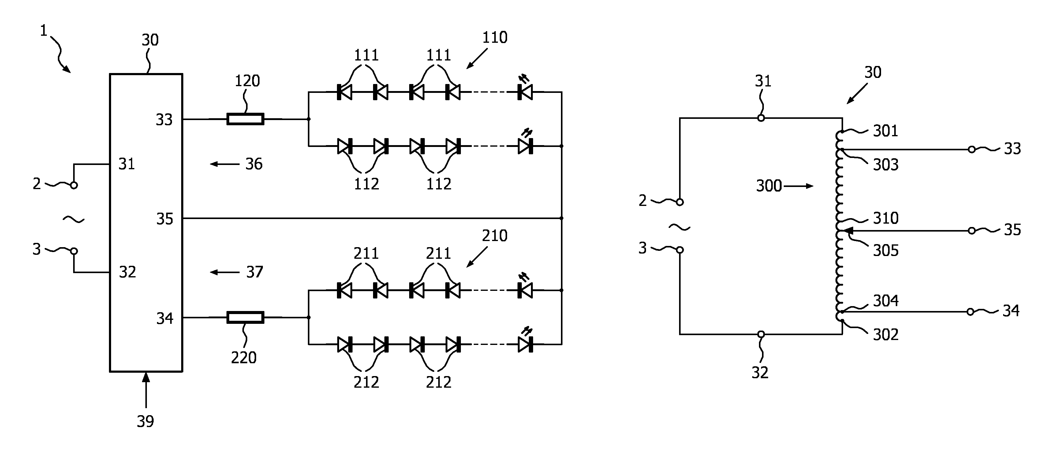
[0012]FIG. 1 schematically shows a block diagram of an illumination device 1 according to the present invention. The illumination device 1 comprises input terminals 2, 3 for coupling to AC mains. The illumination device further comprises a voltage source 30 having two input terminals 31, 32 connected to the input terminals 2, 3 of the illumination device 1, and having three output terminals 33, 34, 35. These output terminals define two outputs of the voltage source 30, one of these terminals, in this case the central terminal 35, being a common terminal. More particularly, a first output terminal 33 together with the common output terminal 35 defines a first output 36 for connecting a load, and a second output terminal 34 together with the common output terminal 35 defines a second output 37 for connecting a load.
[0013]A first string 110 of LEDs is connected in series with a first resistor 120, and this series arrangement is connected to the first output 36 of the voltage source 30....
PUM
 Abstract
Description
Claims
Application Information