Method and apparatus for performing cementing operations on top drive rigs

a technology for drilling rigs and cement heads, applied in the direction of drilling casings, drilling pipes, borehole/well accessories, etc., can solve the problems of high cost, inconvenient and/or otherwise undesirable, and difficult time-consuming to separate the various components of the cement head, so as to eliminate significant risks, easy and efficient connection and/or disconnect, and quick and efficient separation of components

Active Publication Date: 2014-01-28
FRANKS INT
View PDF1 Cites 32 Cited by
  • Summary
  • Abstract
  • Description
  • Claims
  • Application Information

AI Technical Summary

Benefits of technology

[0019]The cement head of the present invention has a high tensile strength, as well as the ability to swivel or rotate about a central (typically vertical) axis. Further, the cement head of the present invention also permits the use of darts, setting plugs, balls, wipers and / or other objects which can be held in place within the cement head without being damaged or washed away by cement slurry flow, but which can be beneficially launched or released into said slurry flow at desired points during the cementing process without slowing down or stopping pumping operations.
[0021]Said upper sub can include a fluid communication swivel assembly that beneficially permits fluid communication from a fluid supply / reservoir (such as a hydraulic fluid supply reservoir) to fluid-driven motors that provide power to actuators. The swivel generally permits the cement head of the present invention to rotate without tangling or breaking of hydraulic lines used to supply such fluid to the fluid-driven motors. At least one remotely actuated control valve can also be mounted at or near the top of said upper sub, and can be used to selectively isolate fluid flow into said cement head. A torque stabilization device can be included to provide a stable platform to prevent lateral movement of said cement head while it is being rotated.
[0023]Once launched, such plugs or other items can move downward into a wellbore below via a tapered funnel-like inner profile. Such plugs or other items are motivated into such wellbore through gravity feed, but can also be assisted by fluid pressure exerted on the plugs or other items from above. As fluid gathers on top and around a launched plug or other item, the tapered funnel inner profile of the cement head of the present invention permits pressure to increase above such plugs or other items, thereby forcing such plug or other item downward into the well bore.
[0024]At least one observation port or window is provided to permit visual observation of objects (such as darts, setting plugs, wipers or the like) that are suspended in a pre-launch static stage. Additionally, at least one open / close indicator provides a visual display to allow observers (including those at or near the rig floor) to determine whether valves are in the fully open or fully closed positions. Plugs (bull plugs and / or blank-off caps) are attached the body of the cement head assembly and may be beneficially removed to confirm proper plug loading before, during or after a job, are held close and prevented from falling by a hinged scissor link pivotally attached to the tool and by a yoke to the bull plug.
[0028]Such connections can be used to quickly and efficiently separate various components of a cement head when access to internal components of such cement head is required at a well location. Although there are many different reasons why such access may be required, common examples include the need to inspect plugs, darts, balls or other objects, or to reload such items within a cement head. Such components can be easily and efficiently connected and / or disconnected at a rig, well site or other remote location by one or two workers without the need for specialized equipment.
[0029]Cement head lines, such as control lines, cement supply lines and torque / rotation tie off lines can all be beneficially attached to the cement head of the present invention while it is on the rig floor. Such lines are kept away from any handling hardware. Further, this capability of the present invention eliminates the need for lifting personnel to an elevated location on a riding belt or basket in order to attach such lines. After all necessary connections are made, the cement head of the present invention is stabbed in place on the rig floor, any remaining connections can also be made on the rig floor. This feature eliminates the need for hardware to be lifted and hammered in place high off of the rig floor, thereby eliminating the significant risks associated with dropped objects.

Problems solved by technology

However, until relatively recently, it has been a challenge to develop a viable method of using top drives systems to make-up and run casing strings, just as strings of drill pipe have historically been run.
As a result, it is typically very difficult and time consuming to separate the various components of a cement head when access to the internal components of such cement head is required at a well location.
Frequently, specialized equipment is needed to connect or disconnect the components of a cement head at a well location, making such operations expensive, inconvenient and / or otherwise undesirable.

Method used


Image

  • Method and apparatus for performing cementing operations on top drive rigs
  • Method and apparatus for performing cementing operations on top drive rigs
  • Method and apparatus for performing cementing operations on top drive rigs

Examples


Embodiment Construction

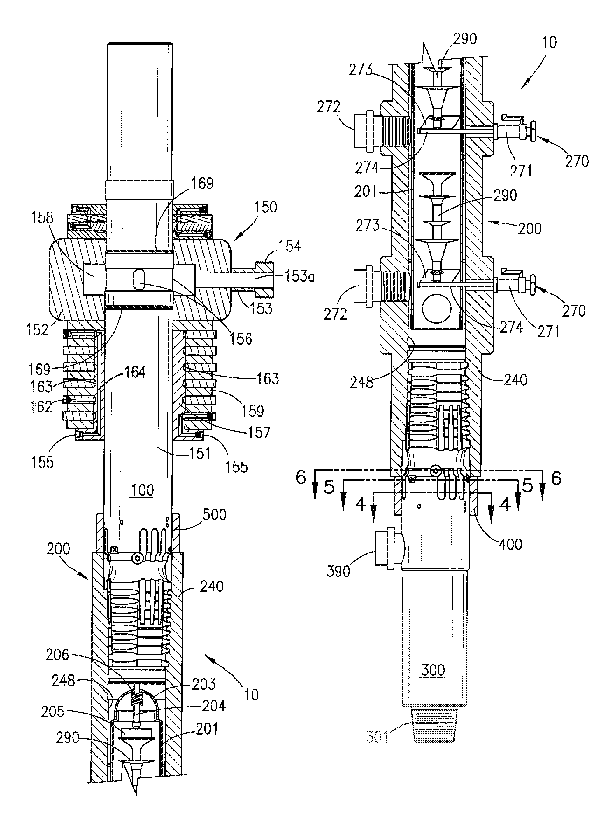
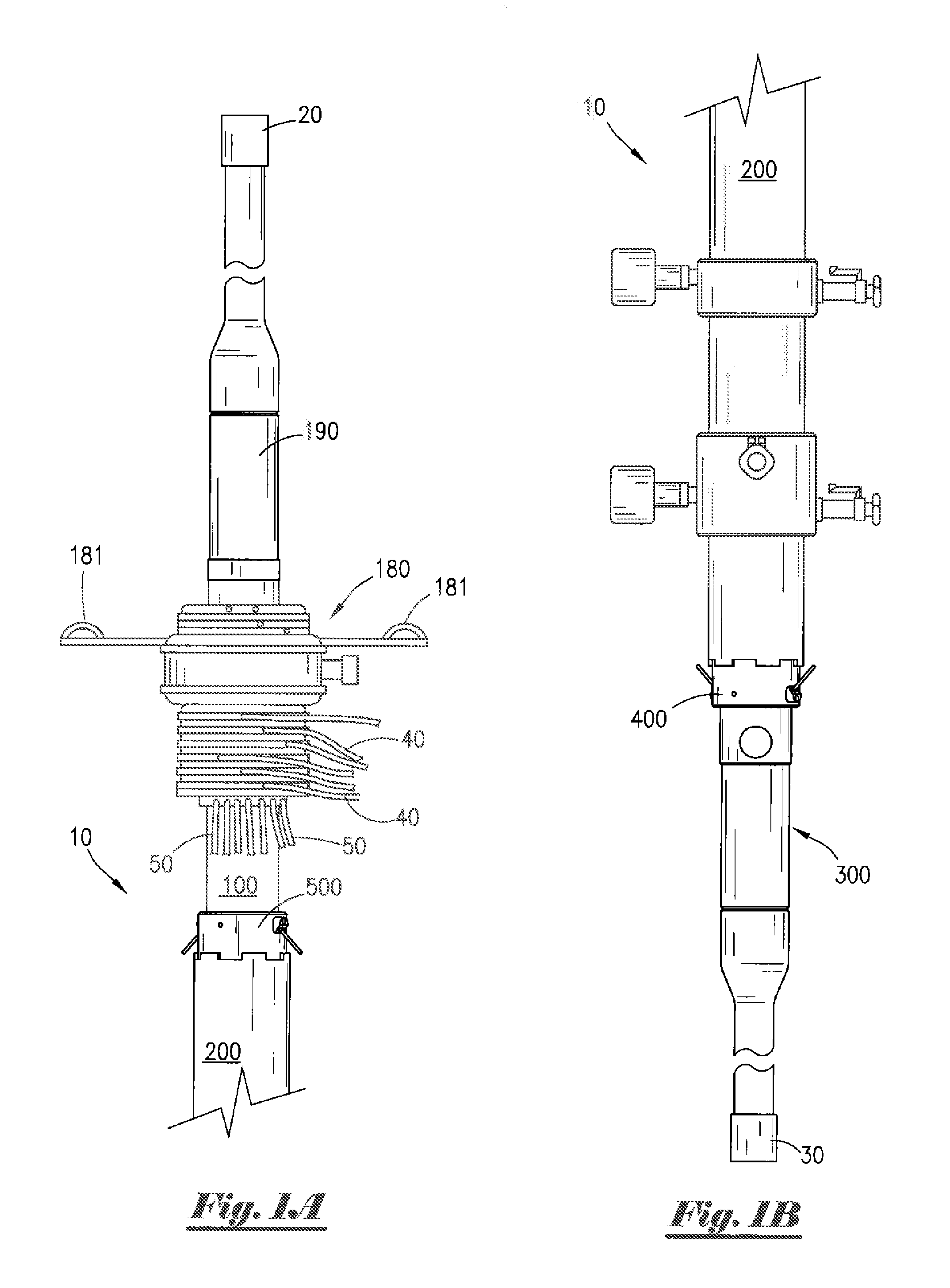
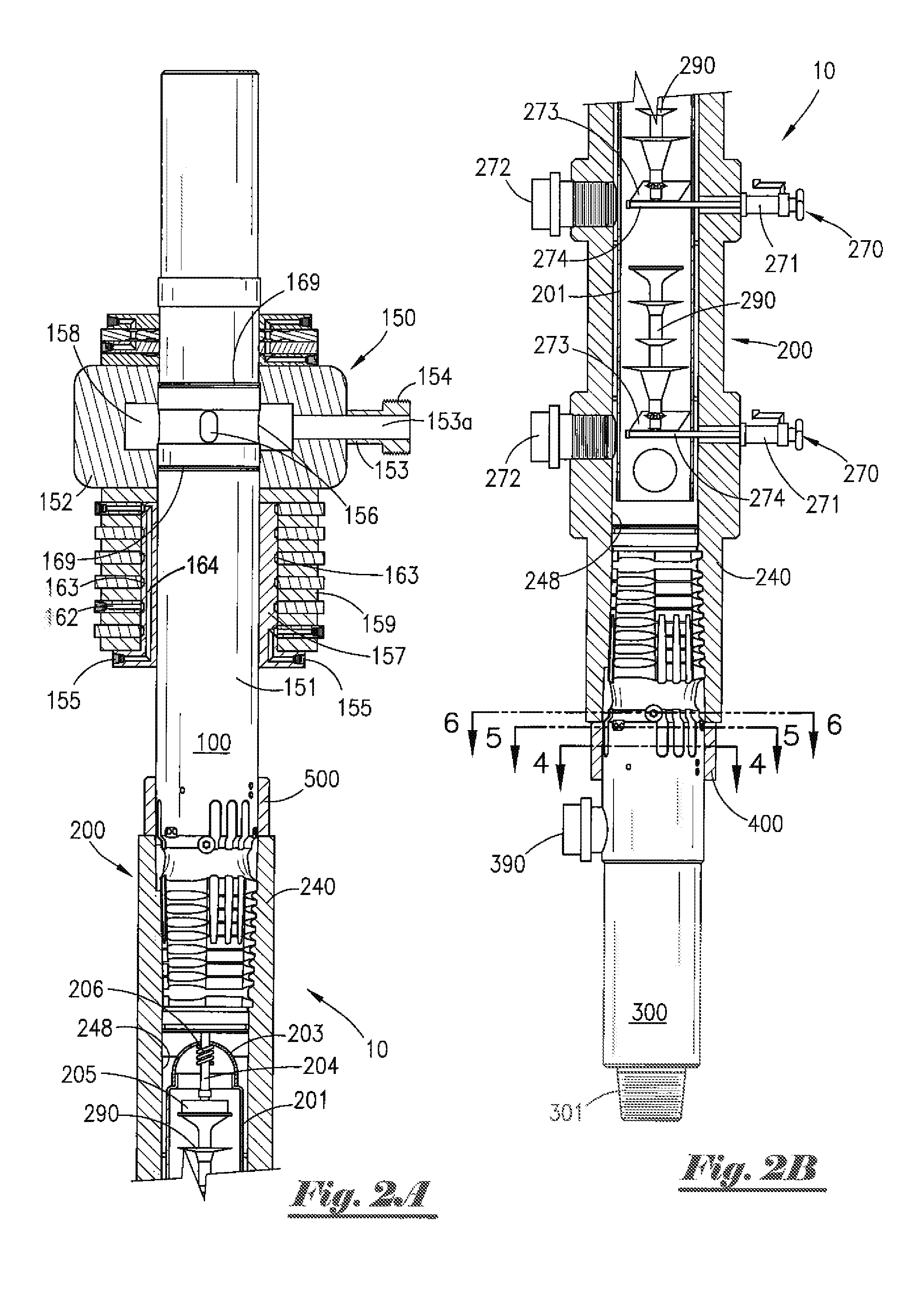
[0055]Existing prior art cement heads typically include valves, dart launching device(s) and / or ball dropper(s) that must be actuated using physical manipulation. As such, when said prior art cement heads are mounted a significant distance above a rig floor, which is frequently required during cementing operations, personnel must be lifted off the rig floor to an elevated location using a makeshift seat or harness attached to a hoist or other lifting device in order to permit such personnel to physically access said cement head in order to actuate valves and / or to launch darts, balls, plugs or other items. In such cases, personnel are placed at great risk of falling and suffering serious injury or death, and can drop wrenches or other heavy tools on people or equipment located on the rig floor below. The cement head of the present invention, which can be connected at the rig floor and actuated remotely, reduces or eliminates many of these risks associated with conventional cement he...


PUM


Abstract

A remotely operated lifting top drive cement head is provided having a high tensile strength, as well as the ability to swivel or rotate about a central vertical axis. The cement head permits selective launching of darts, setting plugs, balls or other objects which can be held in place within the cement head without being damaged or washed away by slurry flow, but which can be beneficially launched into said slurry flow at desired point(s) during the cementing process. The internal components of the cement head can be easily accessed using interrupted thread connections that can be quickly and easy connected and disconnected in the field without requiring specialized equipment. The cement head can be rigged up and remotely operated without requiring the lifting of personnel off the rig floor to actuate the tool or observe tool status.

Description

CROSS REFERENCES TO RELATED APPLICATION[0001]Priority of U.S. Provisional Patent Application Ser. No. 61 / 275,376 filed Aug. 28, 2009, incorporated herein by reference, is hereby claimed.STATEMENTS AS TO THE RIGHTS TO THE INVENTION MADE UNDER FEDERALLY SPONSORED RESEARCH AND DEVELOPMENT[0002]NONEBACKGROUND OF THE INVENTION[0003]1. Field of the Invention[0004]The present invention pertains to a method and apparatus for performing cementing operations in oil or gas wells. More particularly, the present invention comprises a method and apparatus for performing cementing operations in oil or gas wells equipped with top drive systems and casing running tools. More particularly still, the present invention pertains to a method and apparatus for performing cementing operations in oil or gas wells using a plug dropping cement head on rigs equipped with top drive systems and casing running tools.[0005]2. Brief Description of the Prior Art[0006]Conventional rotary drilling rigs typically compr...

Claims


Application Information

Patent Timeline
Patent Type & Authority Patents(United States)
IPC IPC(8): E21B33/05E21B23/08E21B19/18
CPCE21B17/05E21B33/05E21B33/14
Inventor ROBICHAUX, RON D.GIEBELER, JAMES F.MONDELLI, JUAN CARLOS E.
Owner FRANKS INT
Why Eureka
Try Eureka