Unlock instant, AI-driven research and patent intelligence for your innovation.

System and method for controlling multiple beams illuminating projected images

Inactive Publication Date: 2014-01-28
MAGIC LANTERN
View PDF14 Cites 16 Cited by
  • Summary
  • Abstract
  • Description
  • Claims
  • Application Information

AI Technical Summary

Benefits of technology

The invention monitors the scanning beams during the projection of images on a screen by using part of the horizontal blanking time. This allows for real-time balancing and maintenance of the beams' response curves and power levels, resulting in a display field without artifacts and at the desired brightness on the screen. The sensors or a masking structure block the beams from reaching the screen during the horizontal blanking time.

Problems solved by technology

A deviation of power or response curve between beams simultaneously writing multiple lines, or variations in power or response curve in the primaries of a combined beam writing a single line, can cause undesirable visible patterns or artifacts on the screen.

Method used


Image

  • System and method for controlling multiple beams illuminating projected images
  • System and method for controlling multiple beams illuminating projected images
  • System and method for controlling multiple beams illuminating projected images

Examples


Embodiment Construction

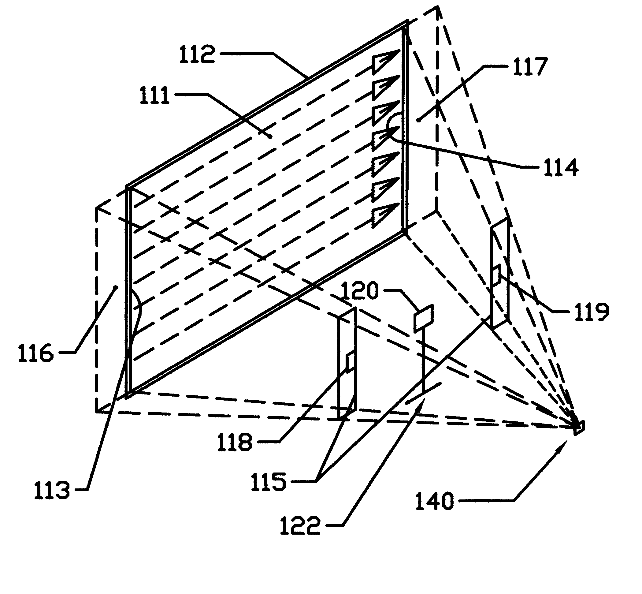
[0014]A preferred embodiment of our invention shown in FIG. 1 is applied to a laser projection system similar to that disclosed in commonly owned U.S. Pat. Nos. 7,102,700 and 7,142,257, each of which is incorporated by reference as though fully set forth herein. The laser projector is schematically represented as scanner 140 in FIG. 1. Although our preferred embodiments invention is illustrated using the multiple-line scanning system disclosed in U.S. Pat. Nos. 7,102,700 and 7,142,257, it should be noted that our invention is applicable to laser projection systems in general. The scanner 140 preferably includes beam source(s) comprised of lasers and modulators for primary colors and in some embodiments beam combiners, scanning components to traverse laser beams from the beam source(s) along a screen, and a controller to control the timing and power level of the beams emitted from the beam source(s) according to pixel and other data to illuminate successive frames on a substantial ar...


PUM


Abstract

The power and response curves of one or more beams or primaries of beams of a laser projection system illuminating an image on a viewing surface are controlled to desired characteristics during exhibition by monitoring the scanning beams in real time by using at least part of the horizontal blanking time during the scanning of a motion or still image to project a test pattern with one or more of the beams onto a sensor or sensors. The system and method permits real-time balancing and maintenance of the response curves and power levels of each of the beams, and of primary beams of combined beams, to desired targets so as to produce a display field without artifacts and at desired brightness on the viewing surface.

Description

PRIORITY DATA & INCORPORATION BY REFERENCE[0001]This application claims the benefit of priority to U.S. Provisional Patent Application No. 61 / 455,207, filed Oct. 15, 2010, entitled “System and Method for Controlling Multiple Beams Illuminating Projected Images” and which is incorporated by reference in its entirety.TECHNICAL FIELD[0002]The present invention relates generally to image projection methods and systems, and more specifically laser projection methods and systems.SUMMARY OF INVENTION[0003]The present invention provides for a method and system for controlling the power and response curves (transfer functions) of one or more beams of a laser projection system illuminating an image on a viewing surface. A deviation of power or response curve between beams simultaneously writing multiple lines, or variations in power or response curve in the primaries of a combined beam writing a single line, can cause undesirable visible patterns or artifacts on the screen.[0004]Preferred emb...

Claims


Application Information

Patent Timeline
IPC IPC(8): G03B21/00G02B26/12G02B7/182G02B26/10G03B21/28G02B26/08G03B21/26
CPCG02B26/0841H04N9/3135G02B26/101G02B26/12H04N9/3129G02B7/182G02B26/08G03B21/00G02B26/10G03B21/26G03B21/28
Inventor CALLISON, JOHN P.PEASE, JEFFREY S.ELLIOTT, GORDON L.
Owner MAGIC LANTERN
Features
  • R&D
  • Intellectual Property
  • Life Sciences
  • Materials
  • Tech Scout
  • Unparalleled Data Quality
  • Higher Quality Content
  • 60% Fewer Hallucinations
Learn More