
Method and device for controlling a light emission of a headlight of a vehicle

a technology for headlights and headlights, which is applied in the direction of lighting support devices, transportation and packaging, lighting and heating devices, etc., to achieve rapid and efficient reduction of abrupt jumps or changes in emission characteristics

Active Publication Date: 2014-01-28
ROBERT BOSCH GMBH
View PDF16 Cites 4 Cited by
  • Summary
  • Abstract
  • Description
  • Claims
  • Application Information

AI Technical Summary

Benefits of technology

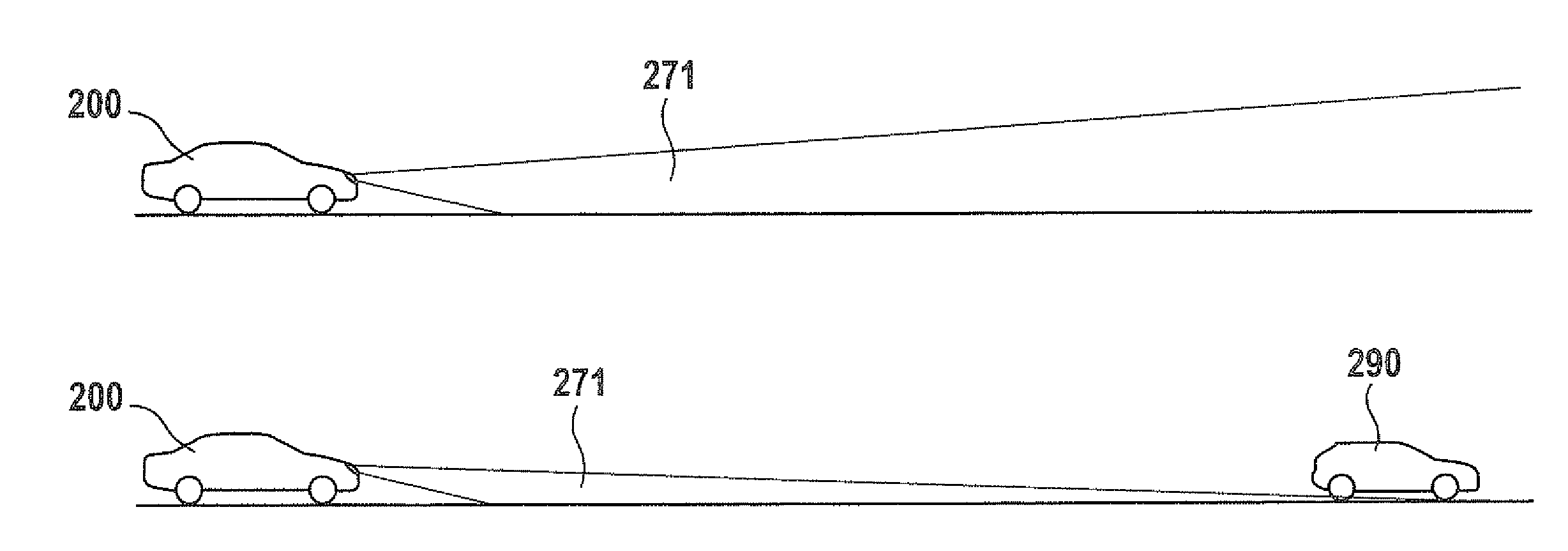
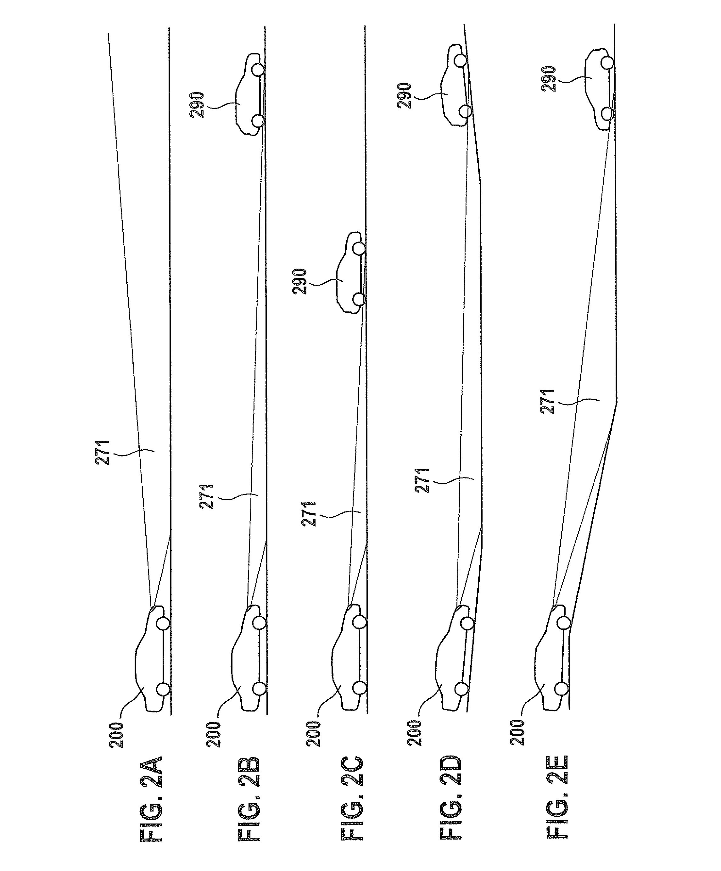
[0007]One advantage of the exemplary embodiments and / or exemplary methods of the present invention is that for the debouncing period or the debouncing distance, an advantageous compromise is found between visual range and proactive avoidance of blinding. Too frequent changing between a high beam and a low beam and an associated interfering effect on driving comfort and vision may be prevented. During the debouncing period or the debouncing distance, which involves proactive waiting between switching between a high beam and a low beam, as a result of the intermediate stage the driver has an improved visual range, and potential blinding of other motorists is avoided. Likewise, inconvenient switching to a low beam when the lights have previously been switched to a high beam and a vehicle appears shortly thereafter may be avoided. Thus, the visual range as well as the safety during the debouncing period or debouncing distance may be increased, and the likelihood of blinding a vehicle which may potentially appear may be minimized. The control is carried out in such a way that, for example, it is convenient for the driver.
[0026]Moreover, the exemplary embodiments and / or exemplary methods of the present invention provide a device which is configured to perform or implement the steps of the method according to the present invention. In particular, the device may have units which are each configured to perform one step of the method. In addition, as a result of this variant of the present invention in the form of a device, the object of the present invention may be achieved quickly and efficiently.

Problems solved by technology

On average, it is not necessary to rapidly switch over and activate the high beam and the low beam as often, which may be easily noticed by the driver and perceived as objectionable, is in particular on the low beam, i.e., when the visual range is reduced.

Method used


Image

  • Method and device for controlling a light emission of a headlight of a vehicle
  • Method and device for controlling a light emission of a headlight of a vehicle
  • Method and device for controlling a light emission of a headlight of a vehicle

Examples


Embodiment Construction

[0035]In the following description of exemplary embodiments of the present invention, identical or similar reference numerals are used for the elements having a similar action which are illustrated in the various figures, and a repeated description of these elements is dispensed with.

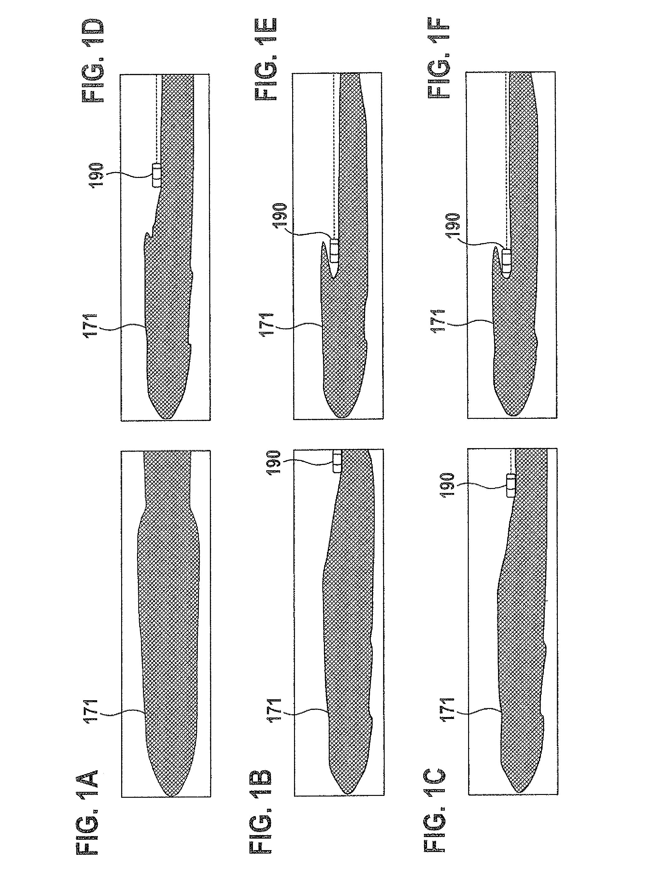
[0036]FIGS. 1A through 1F show schematic illustrations of various emission characteristics 171 of vehicle headlights. The emission characteristics 171 are represented as light distributions or coverage ranges or illumination ranges of vehicle headlights. Specifically, the various emission characteristics 171 may be adjusted with the aid of a high beam assistance system such as adaptive high beam control (AHC), for example. Emission characteristics 171 are shown from an aerial perspective. In FIGS. 1A through 1F, emission characteristics 171 are generated in each case by headlights of a vehicle (not shown), such a vehicle being situated at the left edge of the figure in each of FIGS. 1A through 1F.

[0037]...


PUM


Abstract

A method for controlling a light emission of at least one headlight of a vehicle. The method includes receiving a change enabling signal for performing a change of the light emission of the at least one headlight from an input emission characteristic to an output emission characteristic during a debouncing period and / or debouncing distance which begin(s) in response to the change enabling signal. The method also includes changing the light emission of the at least one headlight from the input emission characteristic to an intermediate emission characteristic in response to the change enabling signal. The method also includes changing the light emission of the at least one headlight from the intermediate emission characteristic to the output emission characteristic after the debouncing period and / or the debouncing distance has / have elapsed.

Description

RELATED APPLICATION INFORMATION[0001]The present application claims priority to and the benefit of German patent application no. 10 2011 081 371.3, which was filed in Germany on Aug. 23, 2011, the disclosure of which is incorporated herein by reference.FIELD OF THE INVENTION[0002]The present invention relates to a method for controlling a light emission of a headlight of a vehicle, and a device which is configured to perform the steps of such a method.BACKGROUND INFORMATION[0003]When controlling the lights in a vehicle with the aid of a known high beam assistance system, debouncing periods or debouncing distances are used, for example to delay activation of the high beam. In this regard, in a high beam assistance system a certain debouncing period or debouncing distance is generally provided to avoid blinding a suddenly (re-)appearing vehicle which briefly disappears behind a curve or hilltop, for example. The debouncing is generally required in all high beam assistance systems. At ...

Claims


Application Information

Patent Timeline
Patent Type & Authority Patents(United States)
IPC IPC(8): B60Q1/00
CPCB60Q2300/324B60Q2300/052B60Q1/085B60Q2300/054B60Q1/143
Inventor EHLGEN, TOBIASFOLTIN, JOHANNESMEISNER, ROBERT
Owner ROBERT BOSCH GMBH
Learn More