Enhanced coaxial connector continuity

a coaxial connector and continuity technology, applied in the direction of coupling device connection, coupling protective earth/shielding arrangement, manufacturing tools, etc., to achieve the effect of reliable ground connection

Active Publication Date: 2014-01-28
PERFECTVISION MFG
View PDF47 Cites 39 Cited by
  • Summary
  • Abstract
  • Description
  • Claims
  • Application Information

AI Technical Summary

Benefits of technology

[0038]Another related object of the present invention to provide a reliable ground connection between a connector and a target socket or port, even if the connector is not fully tightened.
[0040]It is still another object of the present invention to provide such a coaxial connector that can be manufactured economically.
[0042]A related object is to provide a connector of the character described that establishes a decent ground during installation of the male connector to the various types of threaded female connections, even though applied torque may fail to meet specifications.
[0044]Another important object is to minimize resistive losses in a coaxial cable junction.
[0048]Another important object is to provide a compression F-connector of the character described that can be safely and properly installed without deformation of critical parts during final compression.

Problems solved by technology

However, since improper or insufficient tightening of the nut during F-connector installation is so common, and since continuity and / or electrical grounding suffer as a result, our design includes adaptations that establish redundant grounding paths.

Method used


Image

  • Enhanced coaxial connector continuity
  • Enhanced coaxial connector continuity
  • Enhanced coaxial connector continuity

Examples


first embodiment

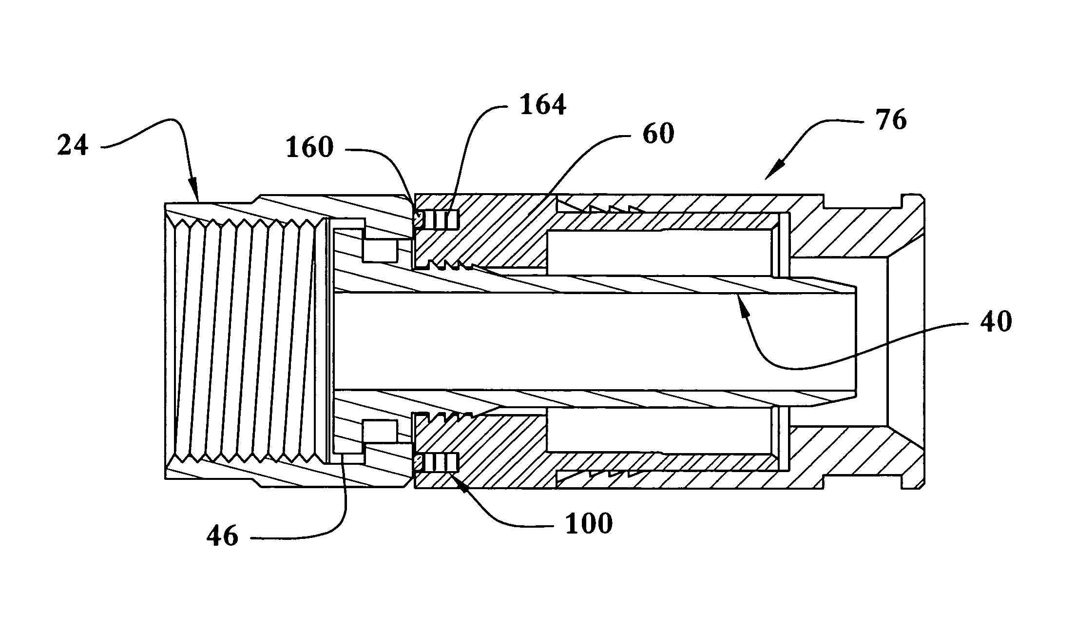
[0081]Therefore our electrical grounding adaptations have been proposed. The first embodiment of our adaptation includes a circumferential groove 100 defined in the body 60 illustrated in FIGS. 3 and 4. Groove 100 is coaxially defined in the outer face of stop ring 62 and, in assembly, faces the nut 24. An annular, generally circular D-ring 102 (i.e., resembling an O-ring) is pressed into groove 100, and, in assembly contacts the nut 24. The cross section of the O-ring reveals a generally band-like, tubular body 104 (FIG. 5) with a forward end 106 with a radiused profile, and a flat rear 105. Thus the preferred O-ring is in the form of a D-ring.

[0082]D-ring 102 presses forward on the F-connector nut 24 with resulting, positive pressure being maintained to tension the contact between post flange 46 and the inner nut shoulder 37 when the nut rotates around the connector during installation. This positive pressure maintains a constant continuity connection between the post and F nut. D...

second embodiment

[0083]A second or alternative embodiment is seen in FIGS. 7-10. Alternative F-connector 23, is externally substantially identical with connector 20, discussed above. However, connector 23 includes a continuity coil described hereinafter instead of O-ring 52. Like connector 20, the alternative connector 23 comprises a nut 24, a post 40, a body 60B, and an end cap 76, all of which are described above. Body 60B, however, lacks a groove 100.

[0084]As best viewed in FIGS. 9 and 10, the continuity coil 110 resembles an O-ring, such as O-ring 52 (FIG. 3) of the last described embodiment. The coil 110 is made of a looped, length of spring wire 114. The body has a circular cross section, indicated by the reference numeral 115 (FIG. 9). Coil 110 sits within post groove 50, and frictionally contacts the peripheral, surrounding wall of passageway 34 in the nut 24, that radially surrounds it. At the same time, post flange 46 contacts nut shoulder 37 (FIG. 8).

[0085]Preferably, continuity coil 110 ...

third embodiment

[0086]A third embodiment is seen in FIGS. 11-12. Alternative F-connector 23B, is externally substantially identical with connector 20, discussed above. However, connector 23B includes both a continuity coil 110 described above, and a D-ring 102. Like connector 20, the alternative connector 23B comprises a nut 24, a post 40, a body 60 and an end cap 76, all of which are described above.

[0087]D-ring 102 is nested within a groove 100 defined in the body 60 as described above. D-ring 102 functions upon assembly to tension the physical contact point between the post 40 and the nut 24. Meanwhile, continuity coil 110, seated within post groove 50 as before, contacts the periphery of nut passageway 34 and the surfaces bordering post groove 50 it establish electrical contact.


PUM

PropertyMeasurementUnit
compressibleaaaaaaaaaa
tensionaaaaaaaaaa
pressureaaaaaaaaaa

Abstract

Axially compressible, F-connectors for conventional installation tools for interconnection with coaxial cable include adaptations for establishing electrical continuity despite inadequate nut tightening. Each connector has a rigid nut, a post penetrating the nut, a tubular body, and an end cap. The conductive post coaxially extends through the connector, linking the nut and body. A post end penetrates the coaxial cable. The connector may have a circumferential groove defined in the end cap mounting an annular D-ring which tensions contact between the post and nut. The connector may comprise a continuity coil seated within a post groove in spring-loaded contact with the nut and the post for promoting continuity. The connector may comprise a pressure spring and an O-ring seated within a post groove in spring-loaded contact with the nut for promoting continuity.

Description

BACKGROUND OF THE INVENTION[0001]1. Field of the Invention[0002]The present invention relates generally to coaxial cable connectors. More particularly, the present invention relates to coaxial F-connectors adapted to insure the establishment of a proper ground during installation. Known prior art is classified in United States Patent Class 439, Subclasses 241, 247, 322, 548, 553, 554, 585, and 587.[0003]2. Description of the Related Art[0004]Popular cable television systems and satellite television receiving systems depend upon coaxial cable for distributing signals. As is known in the satellite TV arts, coaxial cable in such installations is terminated by F-connectors that threadably establish the necessary signal wiring connections. The F-connector forms a “male” connection portion that fits to a variety of receptacles, forming the “female” portion of the connection.[0005]F-connectors include a tubular post designed to slide over coaxial cable dielectric material and under the out...

Claims


Application Information

Patent Timeline
Patent Type & Authority Patents(United States)
IPC IPC(8): H01R9/05
CPCH01R13/652H01R9/05H01R13/5202B23P19/04Y10T29/49963
Inventor CHASTAIN, ROBERT J.SHAW, GLEN DAVID
Owner PERFECTVISION MFG
Why Eureka
Try Eureka