Reference current generating circuit, reference voltage generating circuit, and temperature detection circuit

a reference voltage and current generation circuit technology, applied in pulse generators, instruments, pulse techniques, etc., can solve the problems of reducing the power supply rejection ratio, the current of the p-channel transistor changes in response, and the current mirror accuracy of the current mirror circuit decreases, so as to achieve high current-mirror accuracy and low power supply voltage operation. , the effect of high accuracy

Inactive Publication Date: 2014-01-28
SEMICON ENERGY LAB CO LTD
View PDF30 Cites 1 Cited by
  • Summary
  • Abstract
  • Description
  • Claims
  • Application Information

AI Technical Summary

Benefits of technology

[0010]Further, a cascode current mirror circuit is known as a circuit which is capable of operating at a low power supply voltage lower than that of the current mirror circuit shown in FIG. 7A. This current mirror circuit is shown in FIG. 7B. In the current mirror circuit shown in FIG. 7B, a voltage higher than or equal to (VthM3+VovM3) is required and Vb≧(VovM3+VthM4+VovM4) and VthM3≧VovM4 need to be satisfied in order to operate p-channel transistors M3 and M4 in a saturation region. Note that VthM3 is a threshold voltage of the p-channel transistor M3; VovM3 is an overdrive voltage of the p-channel transistor M3; VthM4 is a threshold voltage of the p-channel transistor M4; VovM4 is an overdrive voltage of the p-channel transistor M4; and Vb is a voltage input from the outside. In general, VthM3 and VthM4 are each about 0.6 V, and VovM3 and VovM4 are each about 0.2 V, and application of a voltage higher than or equal to 0.8 V is necessary and Vb needs to be higher than or equal to 1.0 V for the operation of the current mirror circuit. Therefore, in the case where the current mirror circuit shown in FIG. 7B is used in the reference voltage generating circuit, it is possible to operate at a low power supply voltage lower than 1.25 V, to improve the current mirror accuracy, and to prevent a decrease in power supply rejection ratio.
[0016]A reference current generating circuit according to one embodiment of the present invention includes a current mirror circuit, which can have high current-mirror accuracy by operation at a low power supply voltage. For this reason, the reference current generating circuit with high accuracy and capable of low power supply voltage operation can be provided. Further, a reference voltage generating circuit or a temperature detection circuit according to one embodiment of the present invention generates a reference voltage using the reference current generating circuit. Consequently, a reference voltage generating circuit or a temperature detection circuit with high accuracy and capable of low power supply voltage operation can be provided.

Problems solved by technology

This leads directly to a decrease in the current mirror accuracy of the current mirror circuit included in the reference voltage generating circuit.
In addition, there is a problem in that the currents of the p-channel transistors change in response to the change in power supply voltages input to the sources of the plurality of p-channel transistors (i.e., a decrease in power supply rejection ratio).

Method used


Image

  • Reference current generating circuit, reference voltage generating circuit, and temperature detection circuit
  • Reference current generating circuit, reference voltage generating circuit, and temperature detection circuit
  • Reference current generating circuit, reference voltage generating circuit, and temperature detection circuit

Examples


Embodiment Construction

[0024]Hereinafter, embodiments of the present invention will be described in detail with reference to the accompanying drawings. Note that the present invention is not limited to the description below, and it is easily understood by those skilled in the art that a variety of changes and modifications can be made without departing from the spirit and scope of the present invention. Therefore, the present invention should not be limited to the descriptions of the following embodiments.

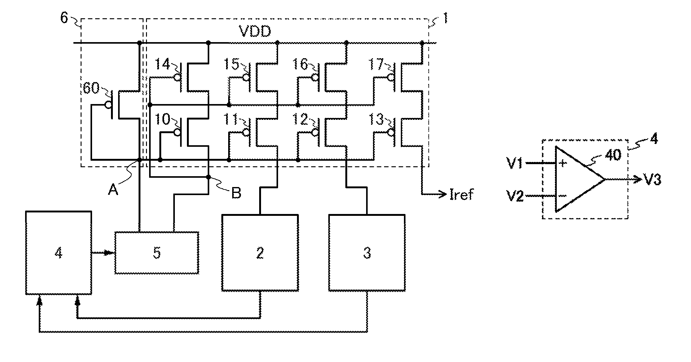
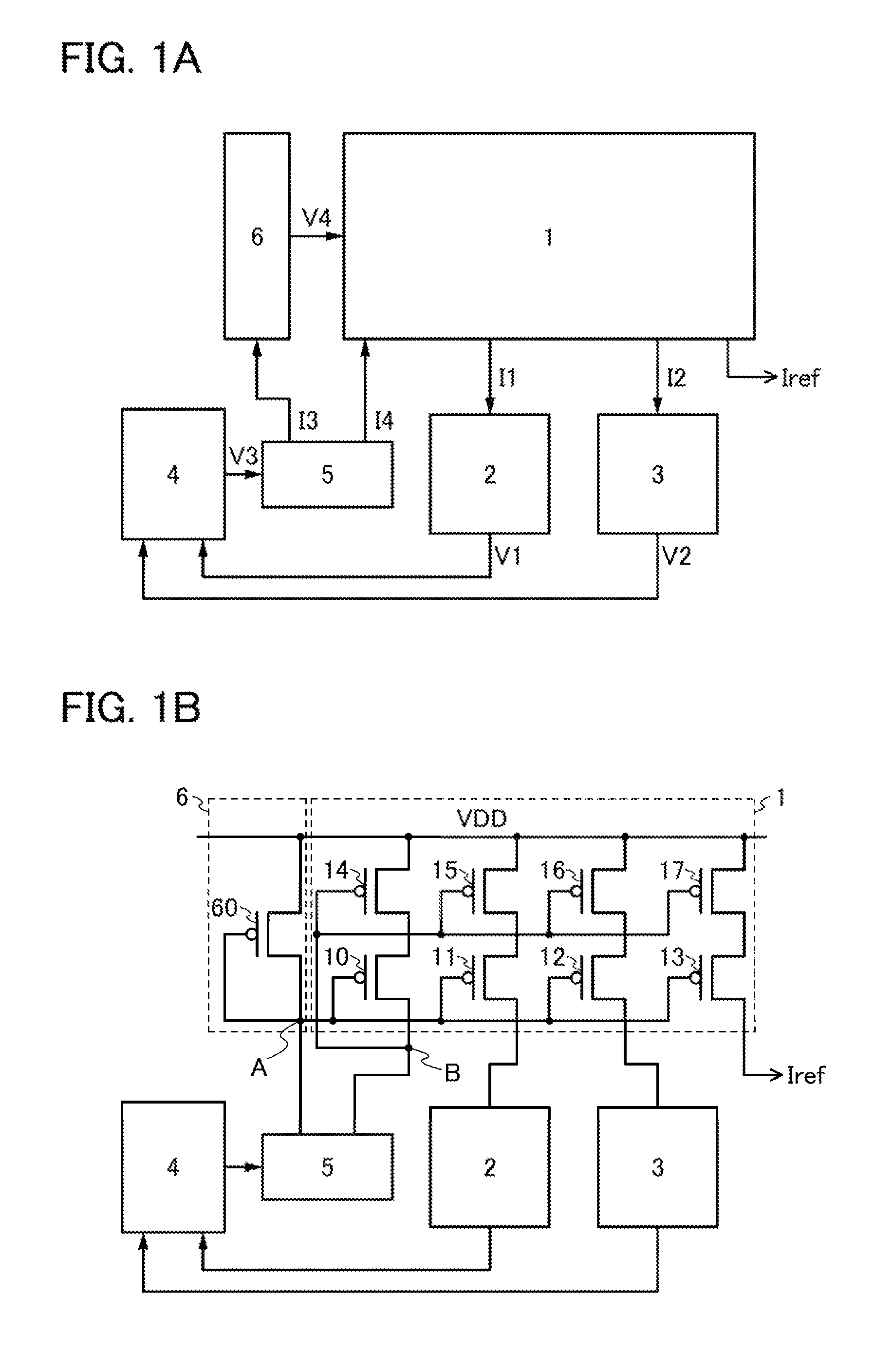
[0025]FIG. 1A is a circuit diagram showing a structural example of a reference current generating circuit according to one embodiment of the present invention. The reference current generating circuit shown in FIG. 1A includes a cascode current mirror circuit 1 outputting a reference current Iref, a current-voltage converter circuit 2 converting a mirror current I1 output from the current mirror circuit 1 into a voltage V1, a current-voltage converter circuit 3 converting a mirror current I2 output from ...


PUM


Abstract

A reference current generating circuit with high current mirror accuracy is provided by low power supply voltage operation. The reference current generating circuit includes a cascode current mirror circuit 1 outputting mirror currents I1 and I2, and a reference current Iref, a current-voltage converter circuit 2 converting the mirror current I1 into a voltage V1, a current-voltage converter circuit 3 converting the mirror current I2 into a voltage V2, a differential amplifier 4 in which the voltage V1 is input to a first input terminal and the voltage V2 is input to a second input terminal, a voltage-current converter circuit 5 converting a voltage V3 output from the differential amplifier 4 into currents I3 and I4, and a current-voltage converter circuit 6 converting the current I3 into a voltage V4 which is output to a gate of a transistor in the cascode current mirror circuit.

Description

BACKGROUND OF THE INVENTION[0001]1. Field of the Invention[0002]The present invention relates to a reference current generating circuit, and a reference voltage generating circuit and a temperature detection circuit using the reference current generating circuit. In particular, the present invention relates to a reference current generating circuit including a MOS transistor, and a reference voltage generating circuit and a temperature detection circuit using the reference current generating circuit.[0003]2. Description of the Related Art[0004]A variety of semiconductor devices requires a reference voltage for operating. As a circuit generating such a reference voltage, a band gap reference circuit is known. A band gap reference circuit can supply a voltage higher than or equal to the band gap of silicon (about 1.25 V) without depending on temperature. Note that the band gap reference circuit was incapable of supplying a voltage lower than the band gap as a reference voltage.[0005]I...

Claims


Application Information

Patent Timeline
Patent Type & Authority Patents(United States)
IPC IPC(8): G05F1/10
CPCG05F3/262G05F3/02G05F3/26
Inventor WATANABE, KAZUNORI
Owner SEMICON ENERGY LAB CO LTD
Why Eureka
Try Eureka