Retransmission mode signaling in a wireless communication system

retransmission mode technology, applied in the field of retransmission mode signaling in a wireless communication system, can solve the problems of inefficient pdsch harq process, inefficient bundling of harq processes, non-bundled or uncorrelated transport blocks, etc., and achieve the effect of reducing or keeping constant the overhead of signaling

Active Publication Date: 2014-01-28
PANASONIC INTELLECTUAL PROPERTY CORP OF AMERICA
View PDF11 Cites 6 Cited by
  • Summary
  • Abstract
  • Description
  • Claims
  • Application Information

AI Technical Summary

Benefits of technology

[0094]Generally, it may be assumed that each codepoint is consisting of a number of N bits. According to another embodiment of the invention, each of the subsets of codepoints is indicating a number of combinations of redundancy versions and new data indicators for the data transmissions that is lower than the maximum number of combinations of redundancy versions and new data indicators for the data transmissions representable by N bits. In other words, the size of the codepoint (i.e. the number of bits thereof) is not simply chosen large enough to signal all possible combinations of redundancy versions and new data indicators for the data transmissions—as a result the signaling overhead can be reduced or kept constant although an additional transmission parameter, the retransmission mode can be signaled.

Problems solved by technology

Furthermore, separate ACK / NACK for each transport block results in the transport blocks being non-bundled or uncorrelated.
This is not efficient from PDSCH HARQ process perspective.
Hence, this bundling of HARQ processes is not efficient, in case if the probability of ACK / NACK of the respective transport blocks is different.

Method used


Image

  • Retransmission mode signaling in a wireless communication system
  • Retransmission mode signaling in a wireless communication system
  • Retransmission mode signaling in a wireless communication system

Examples


Embodiment Construction

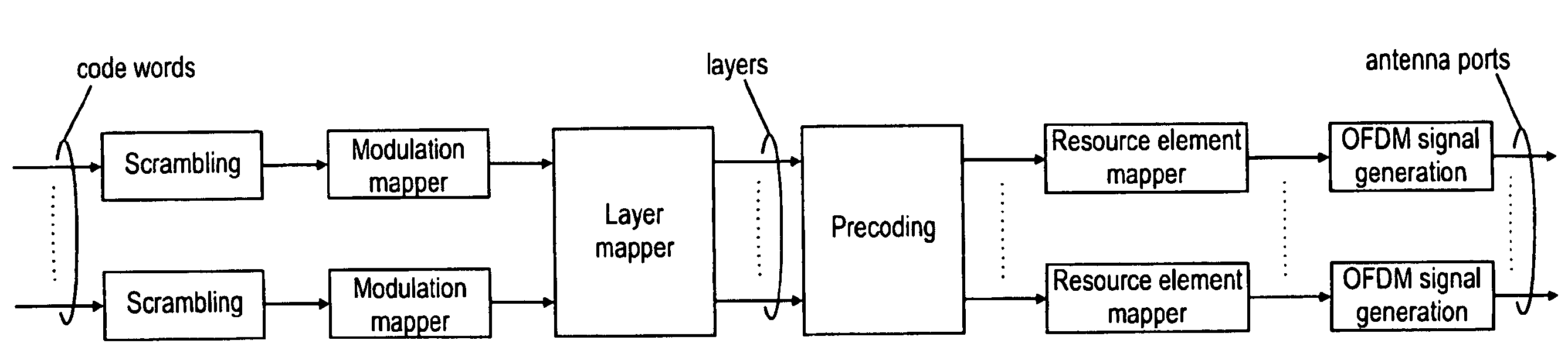
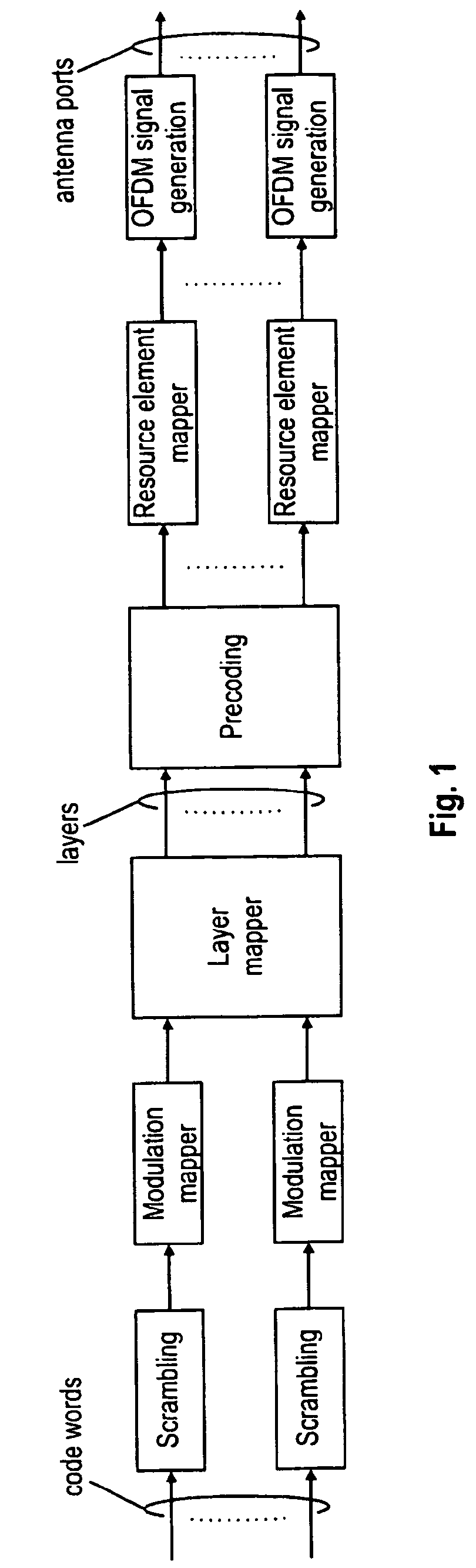
[0150]The following paragraphs will describe various embodiments of the invention. For exemplary purposes only, most of the embodiments are outlined in relation to an (evolved) communication system according to LTE and its currently developed advancements discussed in the Technical Background section above.

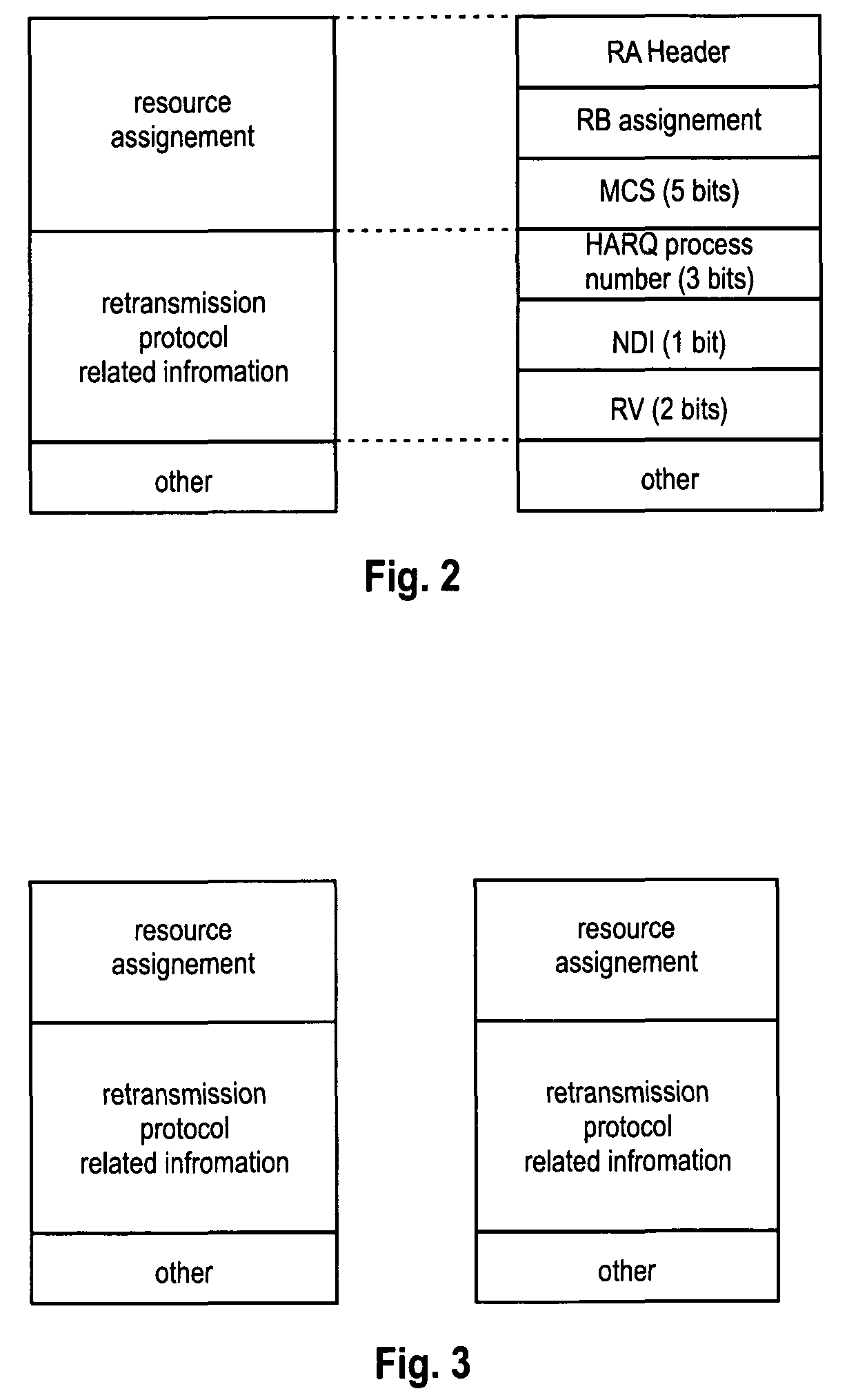
[0151]One aspect of the invention is to suggest a control message format that allows signaling a retransmission mode of a retransmission protocol for a plurality of data transmissions. The control message comprises a field that can be used to indicate a plurality of different codepoints. The codepoints that can be represented by the field (i.e. the values that can be indicated by the given number of bits forming the field in the control message) are divided into at least two subsets, wherein the codepoints of each subset indicate a respective retransmission mode.

[0152]Furthermore, according to another aspect, the meaning of codepoints may differ from each other depending on the su...


PUM


Abstract

The invention relates to a method for determining a retransmission mode of a retransmission protocol for data transmissions provided to a communication terminal. Furthermore, the invention relates to the operation of the communication terminal, e.g. a user equipment or relay node, to perform such method, as well as a Node B cooperating with the communication terminal. The invention is inter alia applicable to a 3GPP LTE-A system as standardized by the 3rd Generation Partnership Project (3GPP). In order to suggest a mechanism for determining or dynamically configuring a retransmission mode of a retransmission protocol, the invention suggests a control message format that allows a dynamic signaling of the retransmission mode of a retransmission protocol. The control message is designed to comprise a field that can indicate a plurality of different codepoints. The codepoints are divided into at least two subsets, wherein the codepoints of each subset indicate a respective retransmission mode.

Description

FIELD OF THE INVENTION[0001]The invention relates to a method for determining a retransmission mode of a retransmission protocol for data transmissions provided to a communication terminal. Furthermore, the invention relates to the operation of the communication terminal, e.g. a user equipment / mobile terminal or relay node, to perform such method, as well as a Node B / base station cooperating with the communication terminal. The invention is inter alia applicable to a 3GPP LTE-A system as standardized by the 3rd Generation Partnership Project (3GPP).TECHNICAL BACKGROUND3GPP Long Term Evolution (3GPP LTE)[0002]Third-generation mobile systems (3G) based on WCDMA radio-access technology, such as UMTS (Universal Mobile Communications System), are currently deployed on a broad scale all around the world. A first step in enhancing or evolving this technology entails introducing High-Speed Downlink Packet Access (HSDPA) and an enhanced uplink, also referred to as High Speed Uplink Packet Ac...

Claims


Application Information

Patent Timeline
Patent Type & Authority Patents(United States)
IPC IPC(8): H04W4/00
CPCH04L1/1887H04L1/1685
Inventor HARIHARAN, PRIYAWENGERTER, CHRISTIAN
Owner PANASONIC INTELLECTUAL PROPERTY CORP OF AMERICA
Why Eureka
Try Eureka