Image forming apparatus with movable pressing member

a technology of forming apparatus and pressing member, which is applied in the direction of electrographic process apparatus, instruments, optics, etc., can solve the problems of affecting the separation mechanism of the entire transfer device from the intermediate transfer belt, and the difficulty of suppressing the position change of the contact region

Inactive Publication Date: 2014-01-28
CANON KK
View PDF7 Cites 1 Cited by
  • Summary
  • Abstract
  • Description
  • Claims
  • Application Information

AI Technical Summary

Benefits of technology

[0007]In view of this, the present invention provides an image forming apparatus having a transfer device including a sheet member and an elastic member, the image forming apparatus capable of suppressing a change in position of the contact region and releasing pressure by the elastic member without separating the entire transfer device from the transfer belt.

Problems solved by technology

However, the configuration in which the transfer device including the sheet member and the elastic member is abutted against and separated from the intermediate transfer belt has a difficulty in suppressing a change in position of the contact region.
The configuration of separating the entire transfer device from the intermediate transfer belt complicates the separation mechanism.

Method used


Image

  • Image forming apparatus with movable pressing member
  • Image forming apparatus with movable pressing member
  • Image forming apparatus with movable pressing member

Examples


first embodiment

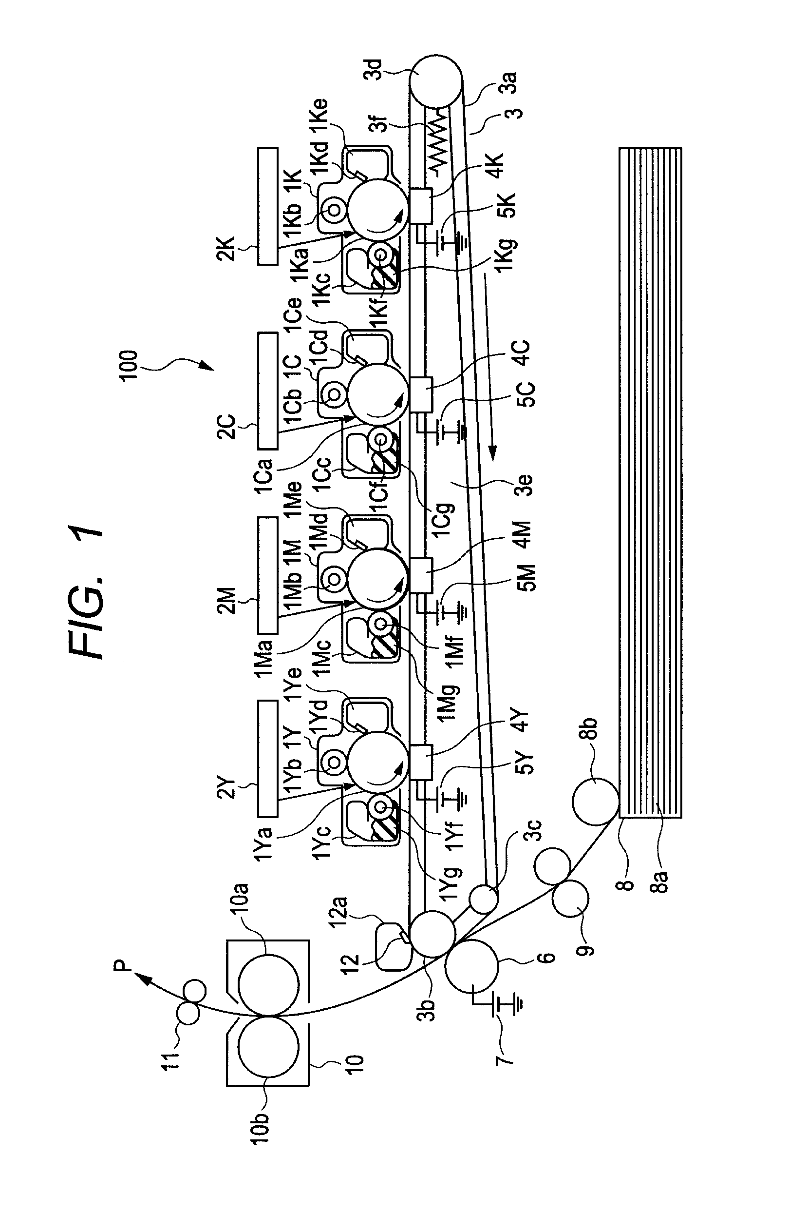
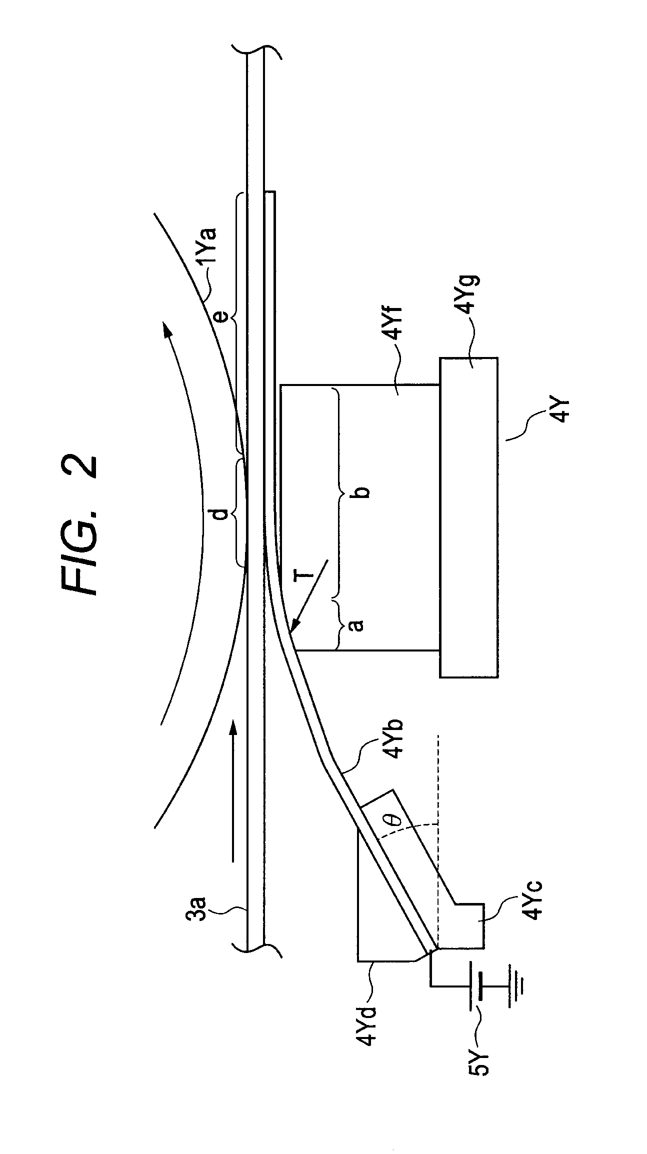
[0020]An image forming apparatus according to a first embodiment of the present invention will be described by referring to the accompanying drawings. FIG. 1 is a configuration diagram of a color image forming apparatus according to the present embodiment. As illustrated in FIG. 1, an image forming apparatus 100 has detachable process cartridges 1Y, 1M, 1C, and 1K. Photosensitive drums (image bearing member) 1Ya to 1Ka are charged by charging rollers 1Yb to 1Kb, and then are exposed by laser units 2Y to 2K to form respective electrostatic latent images. The respective electrostatic latent images are developed by developing rollers 1Yf to 1Kf using toner 1Yg to 1Kg in developing containers 1Yc to 1Kc to form respective color toner images.

[0021]An intermediate transfer belt unit 3 includes an endless intermediate transfer belt 3a as the transfer belt and three tension rollers (a drive roller 3b, a secondary transfer facing roller 3c, and a belt tension roller 3d). A bias with a polari...

second embodiment

[0053]Now, a second embodiment of the image forming apparatus according to the present invention will be described by referring to the accompanying drawings. Note that the same reference numerals or characters are assigned to the components that have already described and the duplicate description is omitted.

[0054]FIGS. 7A and 7B describe a pressing force change operation according to the second embodiment. FIG. 7A illustrates a movement trajectory of the elastic member 4Yf when the pressure force is reduced. FIG. 7B illustrates a movement trajectory of the elastic member 4Yf when the pressure force is increased.

[0055]FIGS. 8A to 8C describe a moving mechanism of the transfer device. FIG. 8A is a configuration diagram of the intermediate transfer belt unit 3 in a low pressure state. FIG. 8B is a configuration diagram of the intermediate transfer belt unit 3 in a full color image forming state. FIG. 8C is a configuration diagram of the intermediate transfer belt unit 3 in a monocolor...


PUM


Abstract

An image forming apparatus includes an image bearing member bearing a toner image, an endless rotatable transfer belt for transferring the toner image from the image bearing member to a transfer material, and a transfer device transferring the toner image from the image bearing member to the transfer belt. The transfer device includes a sheet member, one end of which is fixed and the other end of which comes in contact with an inner peripheral surface of the transfer belt, and a pressing member for pressing the sheet member to the transfer belt. In addition, a moving unit moves the pressing member in a moving direction of the transfer belt so that a contact state of the sheet member with respect to the transfer belt is changed.

Description

BACKGROUND OF THE INVENTION[0001]1. Field of the Invention[0002]The present invention relates to an image forming apparatus transferring a toner image to a transfer material.[0003]2. Description of the Related Art[0004]Conventionally, there has been known an image forming apparatus having a plurality of photosensitive drums arranged laterally in a line and having an intermediate transfer belt as a transfer belt or a conveyor belt conveying a transfer material. Japanese Patent Application Laid-Open No. 2009-048051 discloses an image forming apparatus having a transfer device including a sheet member and an elastic member, wherein the elastic member presses the sheet member to the intermediate transfer belt at a position facing a photosensitive drum so as to be stably in contact with each other to form a desired nip portion. In comparison with a transfer device contacting a transfer roller with the intermediate transfer belt, the transfer device including the sheet member and the elas...

Claims


Application Information

Patent Timeline
Patent Type & Authority Patents(United States)
IPC IPC(8): G03G15/08
CPCG03G2215/0132G03G15/0178G03G15/161G03G15/0194
Inventor NISHIZAWA, YUKI
Owner CANON KK
Why Eureka
Try Eureka