Building roof fascia, coping and/or solar panel connector arrangement

a technology for building roofs and connectors, which is applied in the direction of heat collector mounting/support, pv power plants, light and heating equipment, etc. it can solve the problems of reducing the life of roofs and buildings, rot and the like, and the outer building wall may get heavily wet, so as to facilitate the change of the shape or contour of the coping, easy and economical use and manufactur

Inactive Publication Date: 2014-02-04
BILGE HENRY H
View PDF16 Cites 40 Cited by
  • Summary
  • Abstract
  • Description
  • Claims
  • Application Information

AI Technical Summary

Benefits of technology

[0018]It is a still further object of the present invention to provide a building roof fascia, coping and solar panel connector arrangement that can easily change the shape or contour of coping secured thereto.
[0019]It is a yet further object of the present invention to provide a building roof fascia, coping and solar panel connector arrangement that can hold heating cables to prevent the formation of ice, icic

Problems solved by technology

In the first place, the coping and/or cleats are secured directly to the sides of the building adjacent the roof without any air space therebetween, which can, over time, result in reduction in the life of the roof and building.
For example, if rain gets into the building, there is no air flow to dry out the building, whereby rot and the like may occur.
Also, the outer building wall may get heavily wet due to rain directed thereon by the fascia system.
Secondly, there are no means to provide for easy adjustment up or down of such coping and/or cleats at the side of the building.
For example, it may be desirable to adjust the height or shape of the coping, and this cannot easily be accomplished with known systems.
Third, there is no easy way to provide an extension of the coping and cleats in such known systems.
Fourth, because the

Method used


Image

  • Building roof fascia, coping and/or solar panel connector arrangement
  • Building roof fascia, coping and/or solar panel connector arrangement
  • Building roof fascia, coping and/or solar panel connector arrangement

Examples


Embodiment Construction

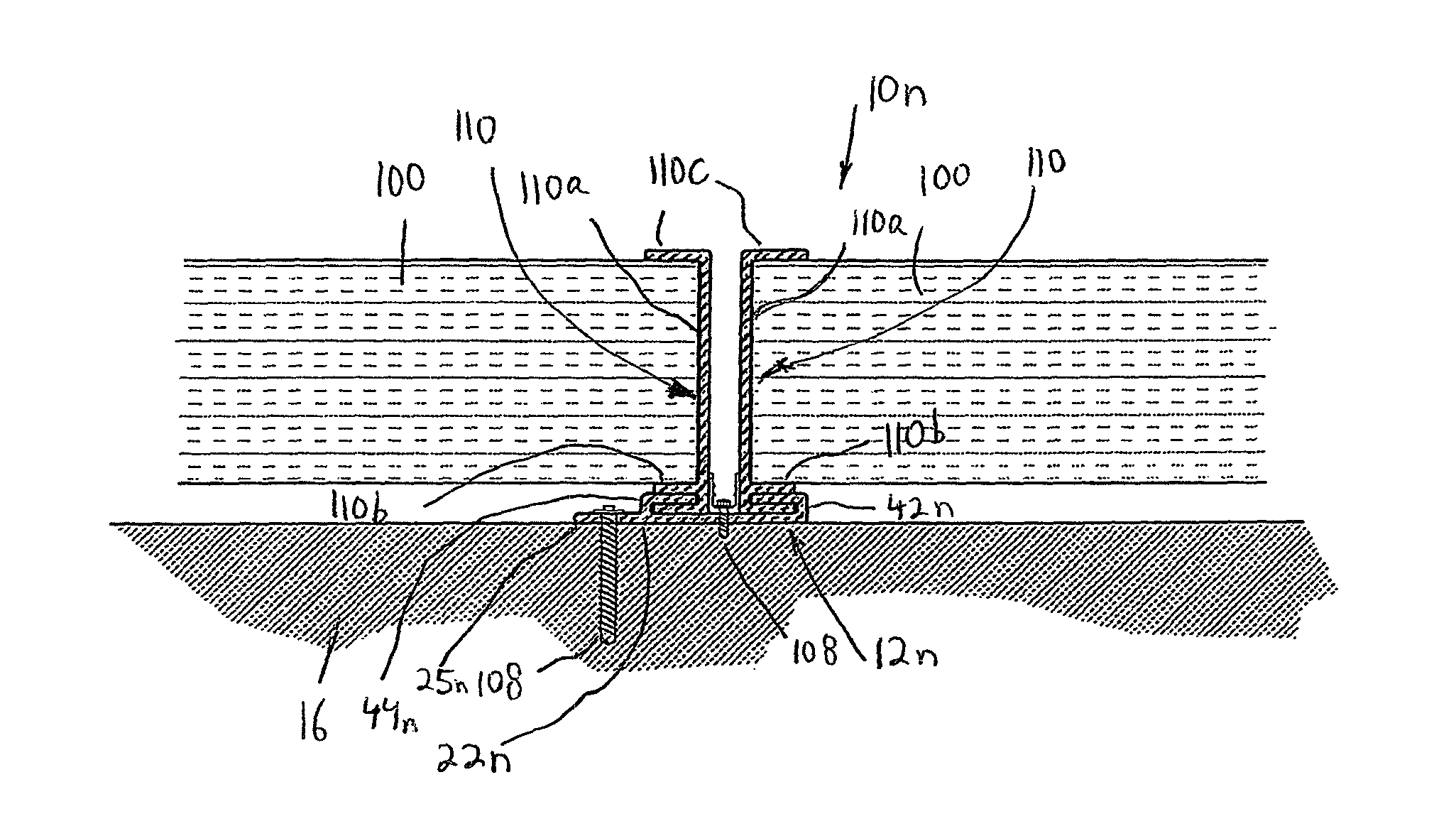
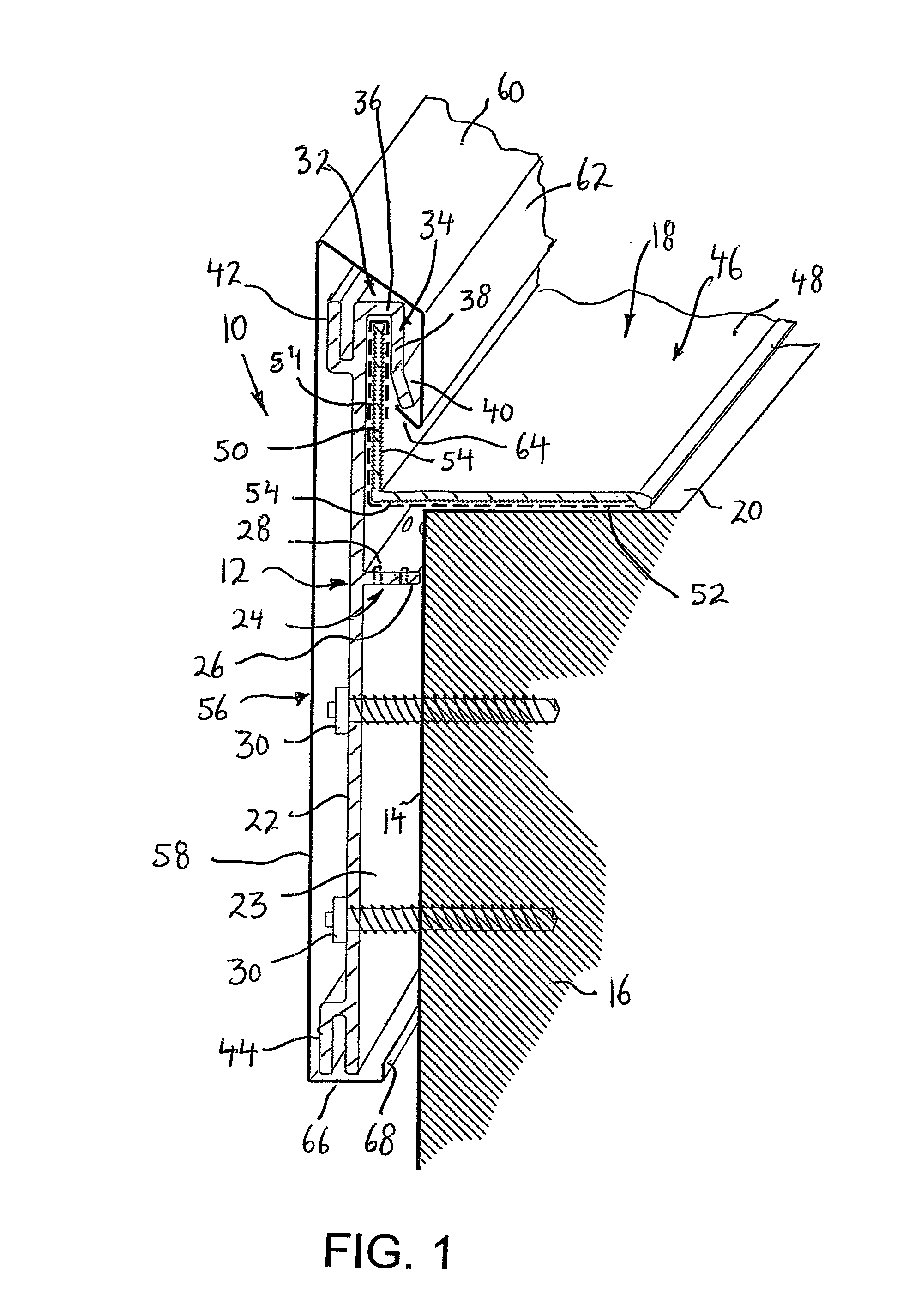
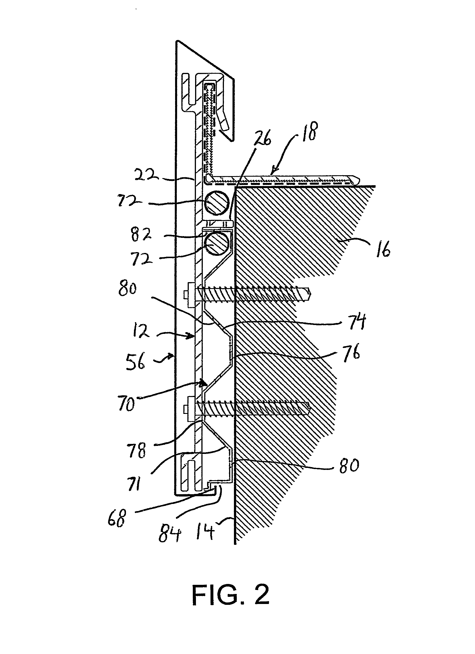
[0076]Referring to the drawings in detail, and initially to FIG. 1 thereof, there is shown a building roof fascia and coping connector arrangement 10 according to the present invention. Building roof fascia and coping connector arrangement 10 includes a cleat 12, preferably formed of aluminum, secured to a side 14 of a building 16, and a vertical load bearing member 18 mounted on the roof 20 of the building 16 and connected with cleat 12.

[0077]Cleat 12 includes an elongated planar wall 22 extending in spaced, parallel relation to building side 14 by a spacer element 24. In FIG. 1, spacer element 24 is a spacer wall 26 formed integrally as one piece with planar wall 22 and extending inwardly at a right angle from planar wall 22, and extending along building side 14. As a result of this arrangement, air flow is provided in the space 23 between building side 14 and planar wall 22, as well as providing air pressure equalization between space 23 and ambient air. In order that spacer wall...


PUM


Abstract

A building roof fascia and coping connector arrangement includes a cleat having a planar wall, a spacer extending inwardly from the planar wall for spacing the planar wall away from a building side when the cleat is secured thereto and having an opening permitting air flow therethrough and between the planar wall and the building, an upper securement assembly at an upper end of the planar wall, and a lower securement assembly at a lower end of the planar wall, with coping secured across an outer surface of the planar wall and connected with the upper and lower securement assemblies; and a vertical load bearing member seating on the building roof when the cleat is secured to the building side, while being connected with an upper end of the cleat to transfer a load from the cleat and the coping to the building roof.

Description

BACKGROUND OF THE INVENTION[0001]The present invention relates generally to building roofs, and more particularly, to connectors for connecting fascia, coping and other elements such as solar panels to building roofs.[0002]As defined herein, fascia refers to elements that are visible at the side of a building and secured to the side of the building adjacent the roof, and can include coping, solar panels or the like. As defined herein, coping is a finishing or protective cap that is secured to a building. If the coping is visible at the side of the building, it is also included in the definition of fascia, but if the coping is on other non-readily visible areas away from the side of the building, it is not included in the definition of fascia. In like manner, if a solar panel is visible at the side of the building, it is also included in the definition of fascia, but may be on other non-readily visible areas from the side of the building, and in such case, is not included in the defi...

Claims


Application Information

Patent Timeline
IPC IPC(8): E04D13/18
CPCE04D13/103E04D3/405E04D13/152F24J2/5245F24J2/045F24J2/5254E04D13/0762E04D13/155F24S20/67F24S25/61F24S25/632Y02B10/20Y02E10/47Y02E10/44
Inventor BILGE, HENRY, H.
Owner BILGE HENRY H
Why Eureka
Try Eureka