Horizontal shackle for lock system and method

a horizontal shackle and lock technology, applied in the field of security systems, can solve the problems of unsuitability of u-shaped shackles, achieve the effects of improving the strength of securement, facilitating or non-destructively releasing, and being more resistant to prying or falling o

Inactive Publication Date: 2014-02-04
DERMAN JAY S
View PDF36 Cites 15 Cited by
  • Summary
  • Abstract
  • Description
  • Claims
  • Application Information

AI Technical Summary

Benefits of technology

[0010]For example, one end of the horizontal member may engage one vertical member with a substantially permanent engagement (e.g., an engagement that cannot be easily or non-destructively released). The other end of the horizontal member may engage the other vertical member with a locking engagement. In certain embodiments, a circumferential groove and a lateral groove may be formed in one end of a horizontal member. A fixed or permanent extension (e.g., pin) may extend from a vertical member to engage the circumferential groove. This locking engagement may improve the strength of the securement provided by the lock, making it more resistant to prying or the like.

Problems solved by technology

However, there are situations or applications where a U-shaped shackle may be unsuitable.

Method used


Image

  • Horizontal shackle for lock system and method
  • Horizontal shackle for lock system and method
  • Horizontal shackle for lock system and method

Examples


Embodiment Construction

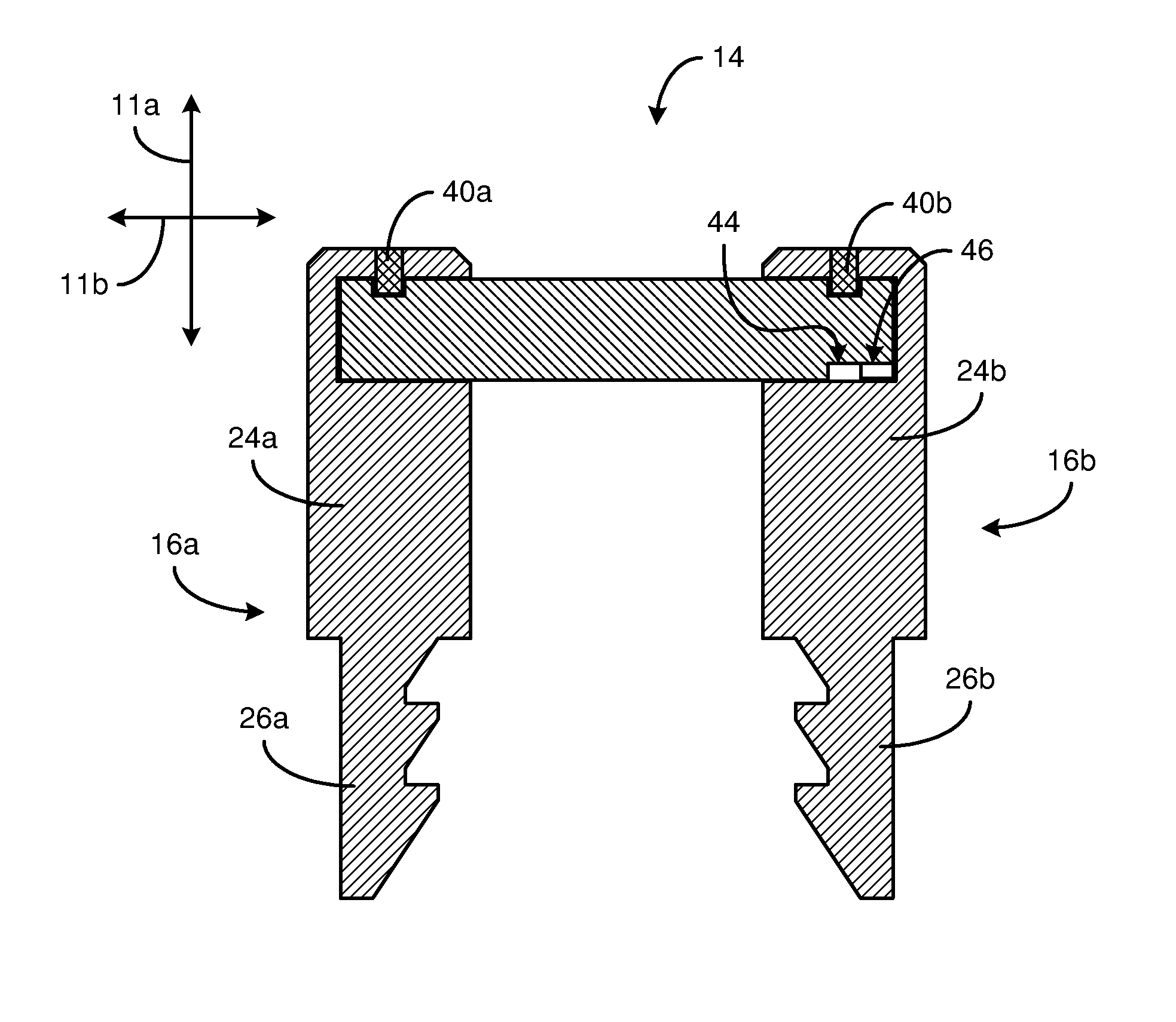
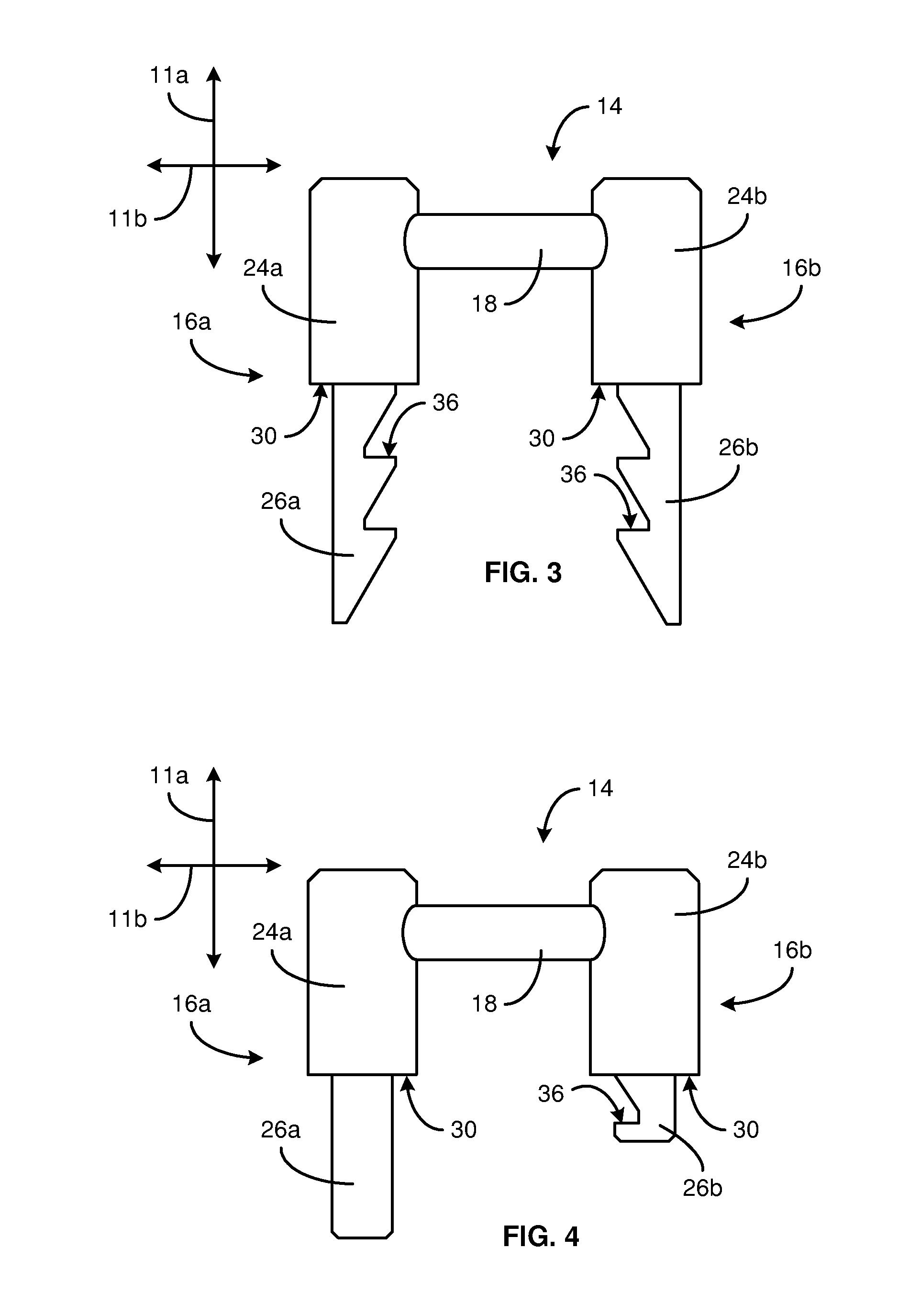
[0039]It will be readily understood that the components of the present invention, as generally described and illustrated in the drawings herein, could be arranged and designed in a wide variety of different configurations. Thus, the following more detailed description of the embodiments of the system and method of the present invention, as represented in the drawings, is not intended to limit the scope of the invention, as claimed, but is merely representative of various embodiments of the invention. The illustrated embodiments of the invention will be best understood by reference to the drawings, wherein like parts are designated by like numerals throughout.

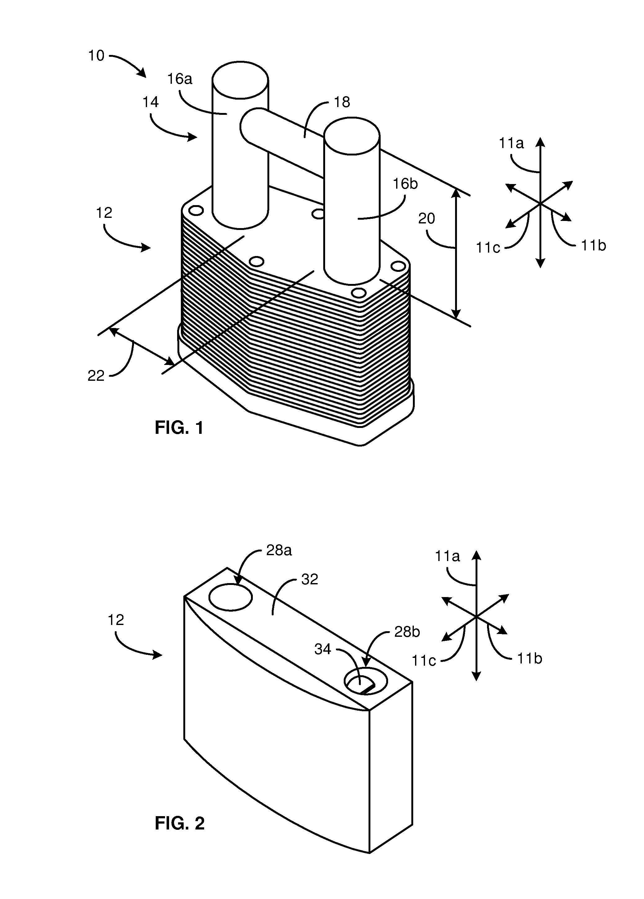
[0040]Referring to FIG. 1, in discussing a lock 10 in accordance with the present invention, it may be beneficial to first establish a reference frame. Accordingly, in selected embodiments, a lock 10 may be said to define a coordinate axes comprising a longitudinal direction 11a, lateral direction 11b, and transverse direction 1...


PUM


Abstract

A padlock having a horizontal shackle is disclosed. The padlock may include a base comprising a latching mechanism, a first shackle aperture, and a second shackle aperture. The padlock may also include a shackle. The shackle may comprise a first post extending from within the first shackle aperture, a second post extending from within the second shackle aperture, and a horizontal cross member extending in a line from the first post to the second post.

Description

RELATED APPLICATIONS[0001]This application claims the benefit of co-pending U.S. Provisional Patent Application Ser. No. 61 / 532,796 filed Sep. 9, 2011, which is hereby incorporated by reference.BACKGROUND[0002]1. The Field of the Invention[0003]This invention relates to security systems and, more particularly, to novel systems and methods for securing personal property or other items.[0004]2. The Background Art[0005]Traditional padlocks include a U-shaped shackle. However, there are situations or applications where a U-shaped shackle may be unsuitable. Accordingly, what is need are improved shackles capable of securing items that are not well suited to traditional shackles.BRIEF SUMMARY OF THE INVENTION[0006]In view of the foregoing, in accordance with the invention as embodied and broadly described herein, a method and apparatus are disclosed in one embodiment of the present invention as including a lock protecting an item from theft, unauthorized use, unauthorized access, unwanted...

Claims


Application Information

Patent Timeline
Patent Type & Authority Patents(United States)
IPC IPC(8): E05B67/06
CPCE05B67/06E05B67/003Y10T70/40E05B67/36Y10T70/441Y10T70/409H01R13/6397Y10T70/491H01R13/443Y10T70/5872Y10T70/452
Inventor DERMAN, JAY, S.
Owner DERMAN JAY S
Why Eureka
Try Eureka