Ramp system for bridging flexible cable to rigid rail

a flexible cable and ramp technology, applied in the field of ramp systems, can solve the problems of increasing the approach angle of any given load, lagging ramp surface, and the same hardness, so as to reduce the approach angle, reduce fatigue, and reduce the effect of cable bending

Active Publication Date: 2014-02-04
PERRY DONALD
View PDF14 Cites 13 Cited by
  • Summary
  • Abstract
  • Description
  • Claims
  • Application Information

AI Technical Summary

Problems solved by technology

The ramp, however, was of the same hardness as the cableway and therefore repeated trolley passage on the ramp rubbed the cable leading to abrasion of the cable.
Also, the ramp lacked a surface modification that would allow a trolley to climb a steeper angle.
However, where there is a cableway having low tension, there would be larger sag which in turn would result in a greater approach angle for any given load.
An additional complication with a low tension cableway is that a self-propelled trolley moves due to contact of the drive wheel with the cable.
When the ramp is steep and / or wet, the drive wheel may lose traction and the trolley will not climb the grade.
Elevated rail systems of one or more rails are expensive to install, since the catenary nature of suspended cables makes trolley movement along them difficult due to the rising and falling of the cableway between supports.
A problem with the high tension cableway is that it needs exponentially larger numbers of supports as the load increases.

Method used


Image

  • Ramp system for bridging flexible cable to rigid rail
  • Ramp system for bridging flexible cable to rigid rail
  • Ramp system for bridging flexible cable to rigid rail

Examples


Embodiment Construction

[0104]The term “about” is used herein to mean approximately, roughly, around, or in the region of. When the term “about” is used in conjunction with a numerical range, it modifies that range by extending the boundaries above and below the numerical values set forth. In general, the term “about” is used herein to modify a numerical value above and below the stated value by a variance of 20 percent up or down (higher or lower).

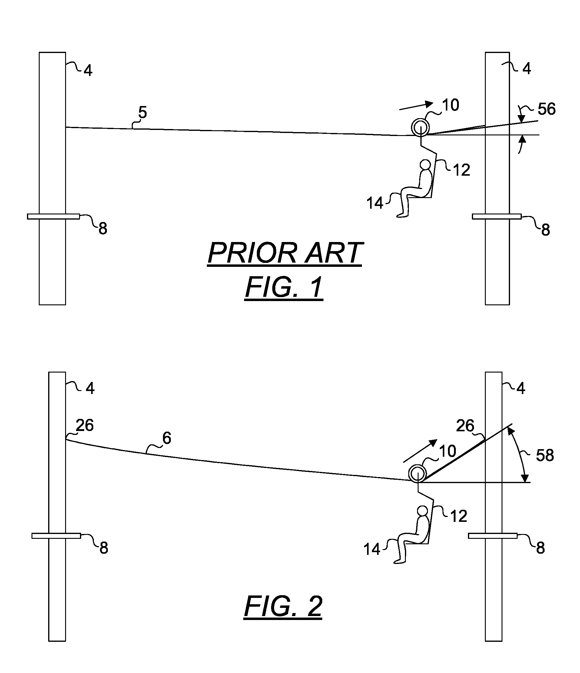
[0105]FIG. 1 is a diagram depicting the prior art use of a high tension cable 5 simply supported at its ends using a support 4 on each end. The cable 5 is spanned between two supports 4 and simply supported at each end with a support 4. The cable 5 is configured for use with a trolley 12 having a drive wheel 10 which comes in contact with and rides on the cable 5.

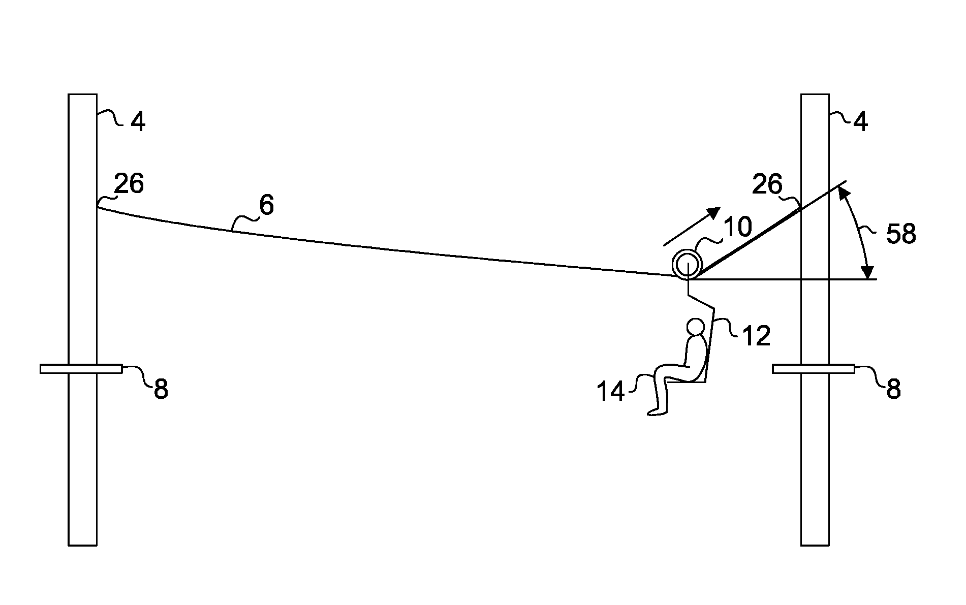
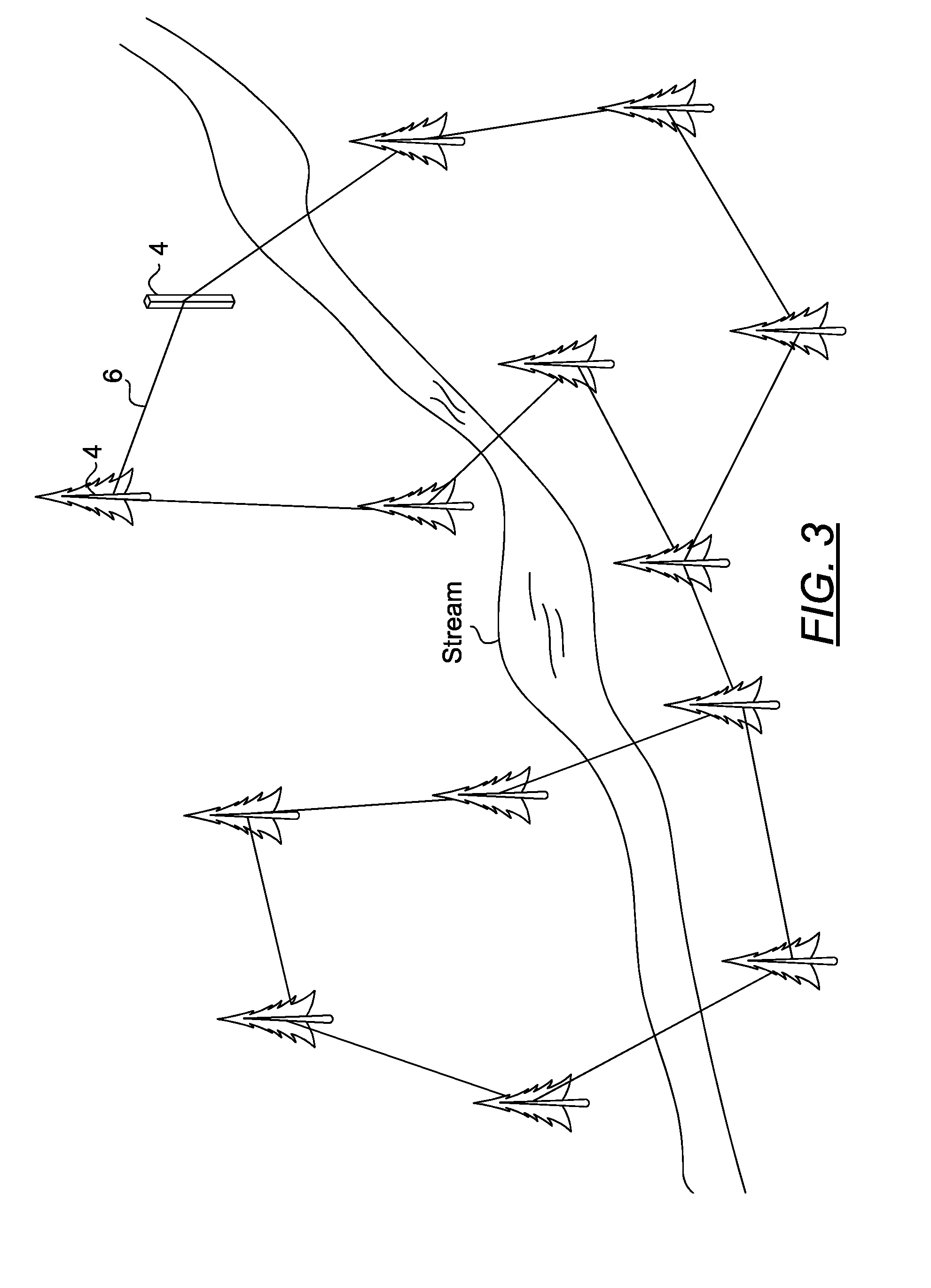
[0106]FIG. 2 is a diagram depicting the use of a low tension cable 6 simply supported at each end using a support 4. FIG. 3 is a diagram depicting a network of cables connecting various erected structur...


PUM


Abstract

A ramp system for bridging a flexible cable to a rigid rail to improve the movement of a trolley along a low tension fixed aerial cableway. The ramp system has an inverted U-shaped elongated channel having a contact surface, a proximal end and a distal end, wherein the distal end is disposed atop and contacts a portion of the cableway and an anchor configured to pivotably support the proximal end of the channel at a second point at a second level. The second level is disposed higher than the first level, wherein the distal end of the channel is slideably but positively secured to the portion of the cable and the first point, second point and distal end cooperate to form a triangular relationship, thereby reducing bending in the cable, reducing the approach angle and fatigue exerted on the channel and cable.

Description

PRIORITY CLAIM AND RELATED APPLICATIONS[0001]This non-provisional application claims the benefit of priority from provisional application U.S. Ser. No. 61 / 561,025 filed on Nov. 17, 2011. Said application is incorporated by reference in its entirety.BACKGROUND OF THE INVENTION[0002]1. The Field of the Invention[0003]The present invention is directed generally to a ramp system. More specifically, the present invention is directed to a ramp system leading from a flexible cableway to a rigid rail to enable the movement of persons or goods to and from the cableway by means of a self-propelled trolley.[0004]2. Background Art[0005]U.S. Pat. No. 2,198,536 to Johansen et al. teaches a moveable rail configured to smooth the transition between a flexible cableway and a rigid rail. The ramp, however, was of the same hardness as the cableway and therefore repeated trolley passage on the ramp rubbed the cable leading to abrasion of the cable. Also, the ramp lacked a surface modification that woul...

Claims


Application Information

Patent Timeline
Patent Type & Authority Patents(United States)
IPC IPC(8): B61B15/00
CPCF16H7/18B61B7/00B61B3/02E01B25/16
Inventor PERRY, DONALD
Owner PERRY DONALD
Why Eureka
Try Eureka