Retrofit for floating roof tanks

a technology for floating roof tanks and vacuum vents, which is applied in the direction of packaging, closures, large containers, etc., can solve the problems of extra inventory held in tank bottoms that cost money, and achieve the effect of reducing inventory heel

Inactive Publication Date: 2014-02-04
MARATHON PETROLEUM
View PDF13 Cites 1 Cited by
  • Summary
  • Abstract
  • Description
  • Claims
  • Application Information

AI Technical Summary

Benefits of technology

[0008]The method of this invention minimizes the inventory heel of a quantity of volatile product stored in the floating roof liquid storage tank. This method comprises the steps...

Problems solved by technology

Extra inventory held ...

Method used


Image

  • Retrofit for floating roof tanks
  • Retrofit for floating roof tanks
  • Retrofit for floating roof tanks

Examples


Embodiment Construction

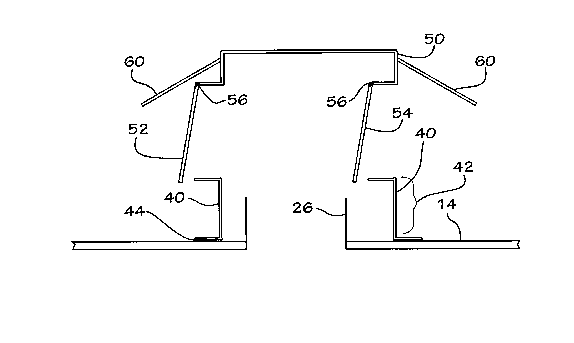
[0013]In the preferred embodiment, the leg-less vent further comprises a frame supporting a pressure door and a vacuum door. A hinge connects the pressure door to the frame and a hinge connects the vacuum door to the frame. The hinges on the vent doors are fabric hinges.

[0014]In a preferred embodiment, the method further comprises the step of: lowering the inventory heel of the volatile product stored in the storage tank.

[0015]The method further comprising the step of: providing necessary pressure or vacuum management to the storage tank.

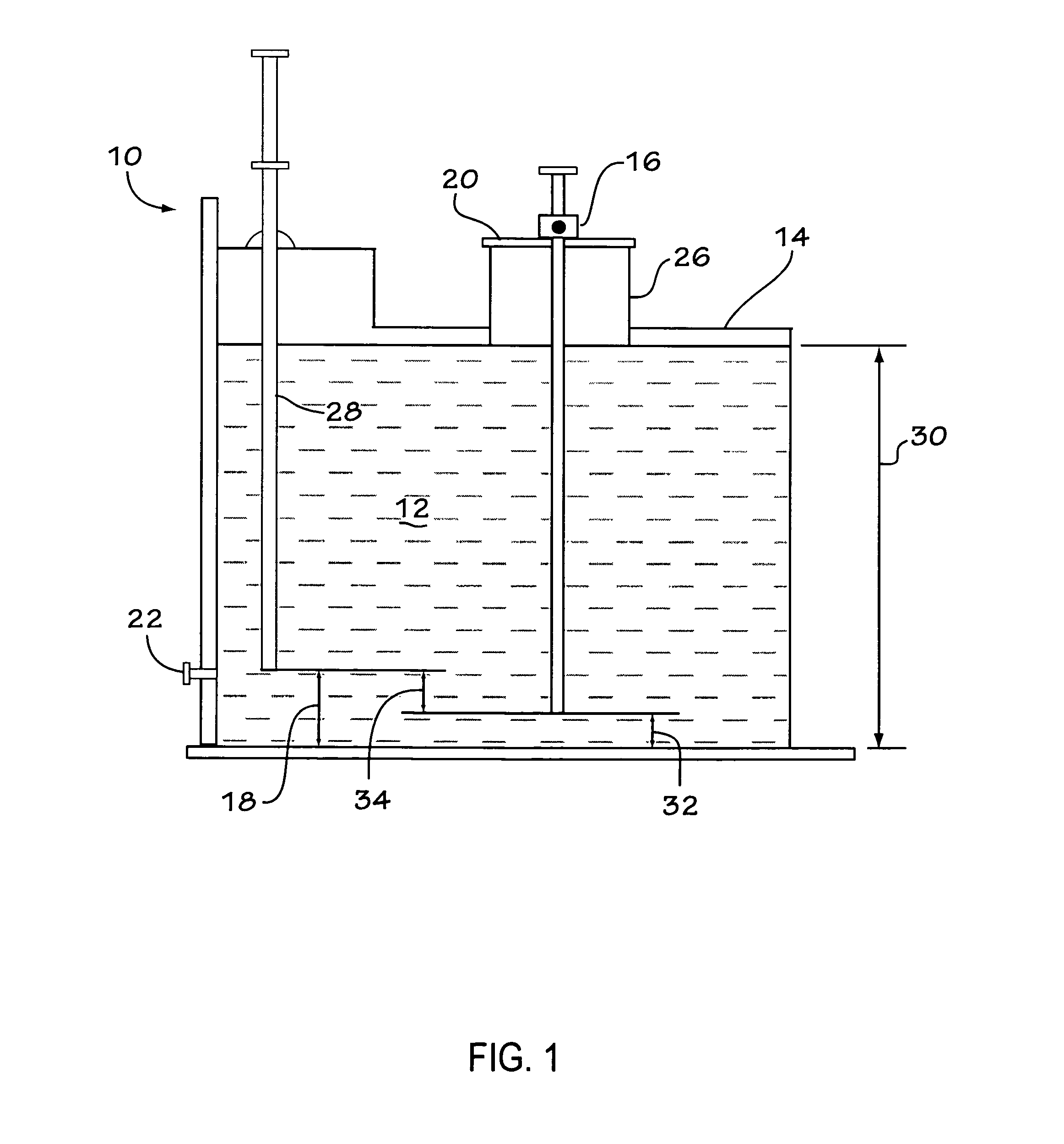
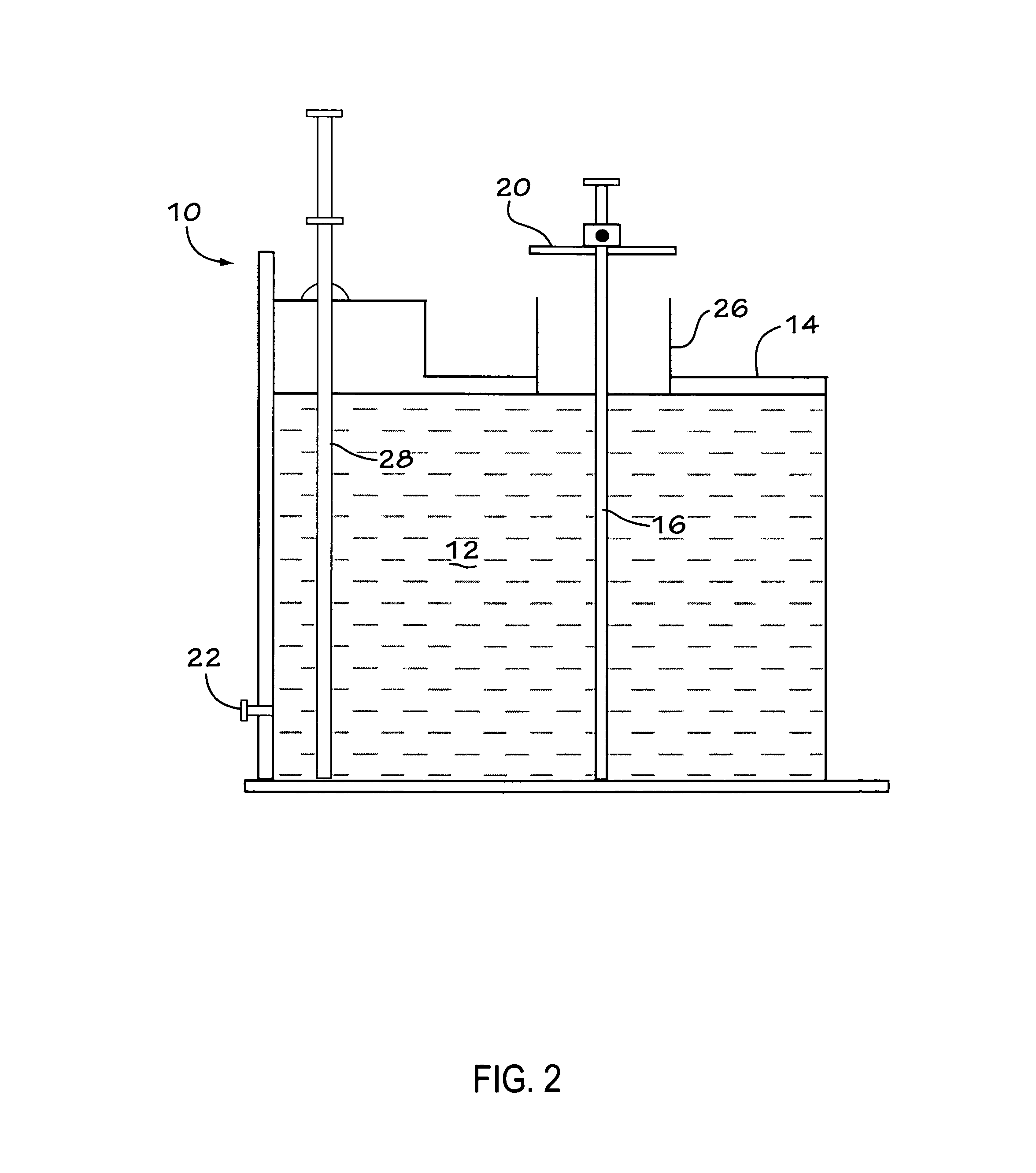
[0016]FIG. 1 is a view showing a typical prior art floating roof tank including a conventional leg-actuated pressure-vacuum vent. FIG. 1 shows the roof floating. FIG. 1 shows a floating roof storage tank 10 that holds a quantity of volatile product 12 therein. There is a floating roof 14 which rests on the product 12 and which is in contact with the product 12. Leg-actuated pressure-vacuum-vent 16 extends through roof 14 and floats on product 12. Th...


PUM


Abstract

Floating roof tanks typically have a leg-actuated pressure-vacuum vent to provide relief upon emptying or filling the space below the roof. This vent leg must hit prior to other legs requiring additional working capital inventory (heel). This retrofit non-leg actuated pressure vacuum (P-V) vent reduces inventory. This P-V vent retrofit provides necessary pressure or vacuum management and at less required tank bottom inventory. The retrofit vent also eliminates the leg-actuated P-V vent.

Description

TECHNICAL FIELD[0001]This invention relates to floating roof liquid storage tanks that are extensively used to store liquid hydrocarbon products such as crude oil, gasoline, and the like. More specifically, the invention relates to a retrofit pressure vacuum vent for floating roof tanks.BACKGROUND OF THE INVENTION[0002]Oil refineries and storage terminals utilize floating roof tanks for the storage of hydrocarbon stocks which have a high vapour pressure. Typical products are gasoline, naphthas and crude oil.[0003]The filling and emptying of the tanks is between a normal minimum to a normal maximum gauge (or depth) which typically is approximately 2 meters to approximately 14 meters respectively. The minimum gauge elevation is determined by the need to keep the underside of the roof clear of any projections into the tank (e.g. tank heaters, mixers, suction / rundown lines) and the requirement to provide sufficient head for pumping equipment connected to the tank. As all working movemen...

Claims


Application Information

Patent Timeline
IPC IPC(8): B65D88/40
CPCB65D88/40
Inventor HERRMANN, GARY
Owner MARATHON PETROLEUM
Why Eureka
Try Eureka