Rolling bearing, in particular radial needle bearing having a labyrinth seal

a rolling bearing and labyrinth seal technology, applied in the direction of bearings, roller bearings, needle bearings, etc., can solve the problems of reducing the life of the needle bearing, increasing the wear of the lip seal, and relatively high assembly costs, so as to achieve economic production and facilitate handling

Inactive Publication Date: 2014-02-04
SCHAEFFLER TECH AG & CO KG
View PDF33 Cites 5 Cited by
  • Summary
  • Abstract
  • Description
  • Claims
  • Application Information

AI Technical Summary

Benefits of technology

[0008]Starting from the disadvantages of the known prior art, it is therefore the underlying object of the invention to design a rolling bearing, in particular a radial needle bearing, which is designed, at least on one side, with an economical and easy-to-install seal which avoids sliding contact with the shaft to be supported.
[0012]In a further embodiment, the sealing ring of smaller diameter has two encircling annular beads on the inner circumferential surface of its inner profile leg to enable it to be fixed on the circumferential surface of the shaft to be supported, and is arranged with its profile web parallel to the thrust washer. The fixing of the sealing ring of smaller diameter on the circumferential surface of the shaft to be supported thus has the effect that the sealing ring is designed as a co-rotating part of the labyrinth seal, while the arrangement of its profile web parallel to, but not in direct contact with the thrust washer is provided to form an additional sealing gap between the profile web and the thrust washer and to simultaneously provide a possibility of compensating slight axial movements of the shaft to be supported.
[0013]In yet another embodiment, the mutually engaging arrangement of the sealing rings of the labyrinth seal is implemented in such a way that, starting from the complementary C-shaped profile cross-sections thereof, the outer profile leg of the sealing ring of smaller diameter is arranged between the profile legs of the sealing ring of larger diameter, and the inner profile leg of the sealing ring of larger diameter is arranged between the profile legs of the sealing ring of smaller diameter. A sealing gap with a number of bends is thereby created between the individual profile legs of both sealing rings, making it possible to achieve a highly effective seal.
[0016]The rolling bearing designed in accordance with the invention thus has the advantage over the rolling bearings known from the prior art that it is designed with a labyrinth seal which can be produced economically, which, on the one hand, avoids sliding contact with the shaft to be supported and, on the other hand, can be integrated into the rolling bearing as a fully assembled modular unit and is easy to handle during assembly of the bearing. Moreover, a labyrinth seal of this kind additionally offers the possibility of use within a U-profile-shaped sheet metal ring as a preassembled single sealing system in other appropriate applications.

Problems solved by technology

However, the disadvantage with radial needle bearings of this kind has proven to be the sealing thereof by means of the sliding contact between the sealing lip of the lip seal thereof and the shaft since this sliding contact usually causes high friction, as a result of which there is increased wear on the lip seal and hence a reduction in the life of the needle bearing.
However, the disadvantage with labyrinth seals designed in this way is that, in the case of needle bearings without an inner ring, as used in support bearings in dual mass flywheels, they cannot be integrated as a modular unit into the bearing, but can only be completed when the bearing is mounted on the shaft and, thus, give rise to relatively high assembly costs.

Method used


Image

  • Rolling bearing, in particular radial needle bearing having a labyrinth seal
  • Rolling bearing, in particular radial needle bearing having a labyrinth seal
  • Rolling bearing, in particular radial needle bearing having a labyrinth seal

Examples


Embodiment Construction

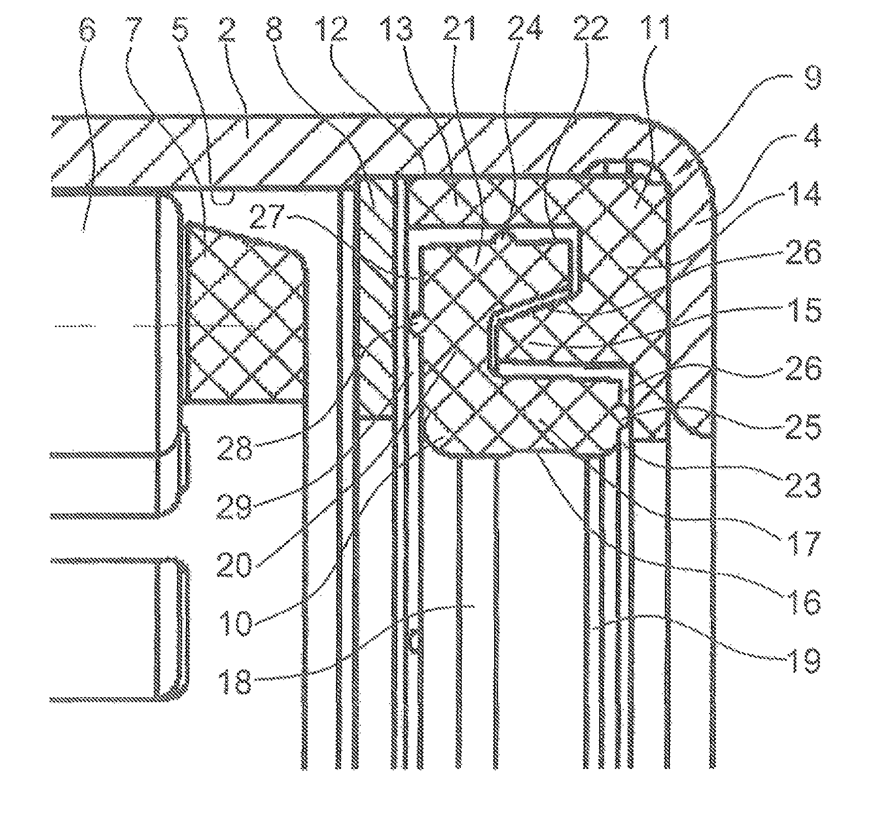
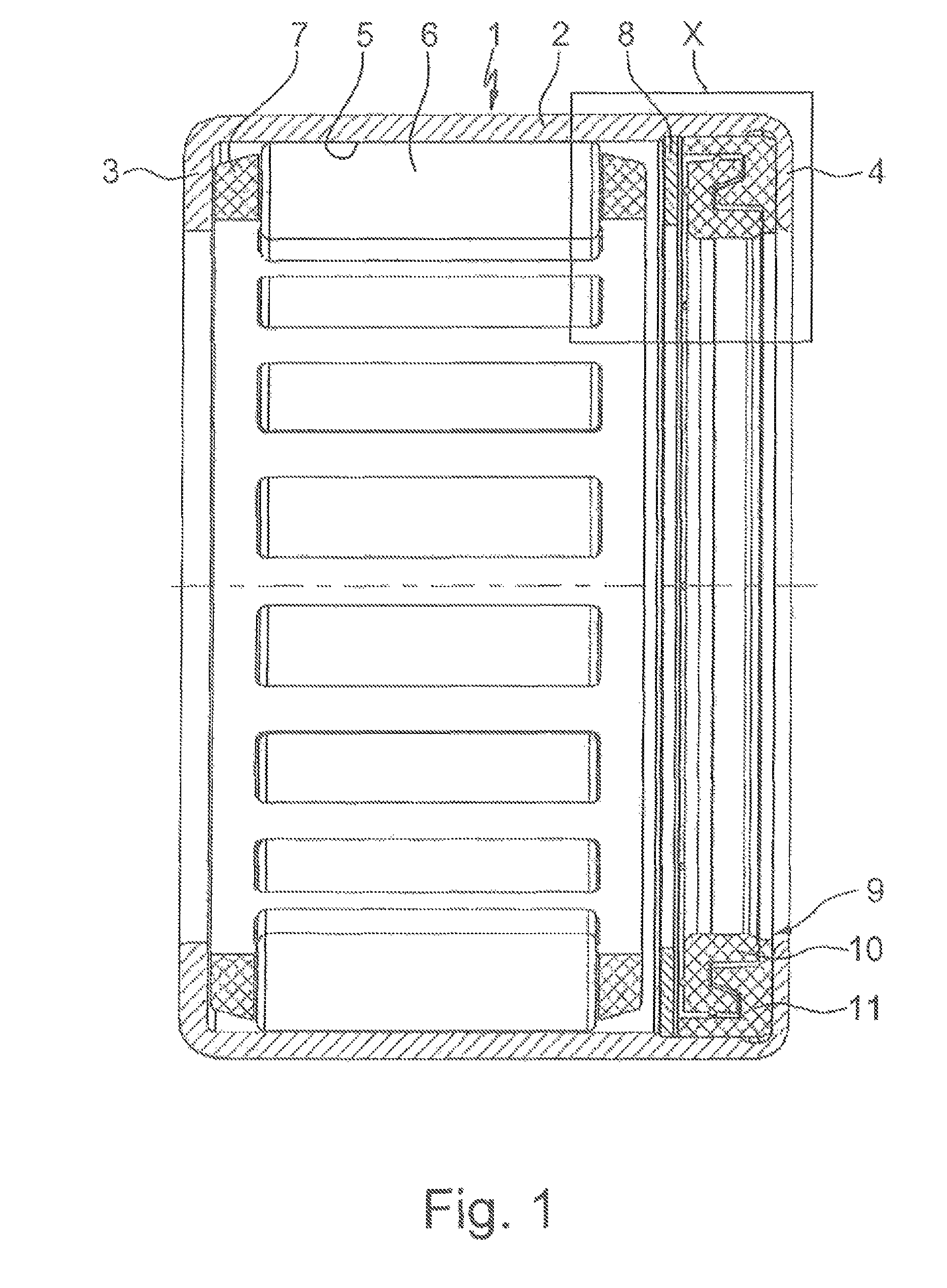
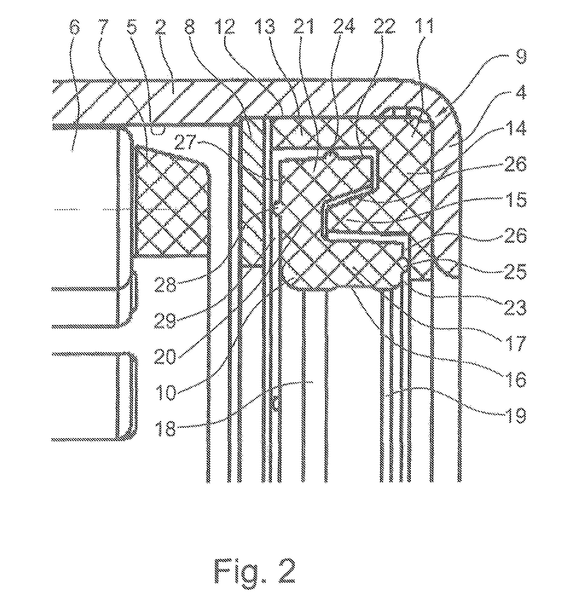
[0020]FIG. 1 clearly shows a radial needle bearing 1, which is suitable for supporting the secondary mass on the primary mass of a dual mass flywheel in a motor vehicle and which consists essentially of a thin-walled outer needle sleeve 2 having radial rims 3, 4 that are axially inwardly directed on both sides, a multiplicity of bearing needles 6 rolling on the inner circumferential surface 5 of the needle sleeve 2 and on the outer circumferential surface of a shaft (not shown), and a needle cage 7, which guides the bearing needles 6 in the circumferential direction in an evenly spaced manner. FIG. 1 also shows that, on one side, adjacent to the needle cage 7, an additional thrust washer 8 is inserted into the needle sleeve 2, which washer is provided to limit the axial mobility of the needle cage 7 together with one radial rim 3 of the needle sleeve 2, and that a sealing element 9, which is provided for sealing off the radial needle bearing 1 on one side, is arranged between the th...


PUM


Abstract

A radial needle rolling bearing, which has a thin-walled outer sleeve with radial rims that are axially inwardly directed on both sides, a plurality of needle bearings rolling on the inner lateral area of the sleeve and on the outer lateral area of the shaft to be supported, and a cage guiding the bearing needles in the circumferential direction in an evenly spaced manner. At least on one side, in addition to the needle cage, an additional stop disc is inserted into the needle sleeve. The disc is delimits axial movability of the needle cage together with a radial rim or a further stop disc inserted into the sleeve. Between the stop disc and the other radial rim, a sealing element is arranged, which seals the bearing. The sealing element is a labyrinth seal, which can be assembled from two individual mutually engaging sealing rings that have complimentary profile cross-sections.

Description

CROSS-REFERENCE TO RELATED APPLICATIONS[0001]This application is a 371 of PCT / EP2010 / 063006 filed Sep. 9, 2010, which in turn claims the priority of DE 10 2009 048 290.3 filed Oct. 5, 2009. The priority of both applications is hereby claimed and both applications are incorporated by reference herein.FIELD OF THE INVENTION[0002]The invention relates to a rolling bearing and more specifically to radial needle bearings to provide support for the secondary mass on the primary mass of a dual mass flywheel in a motor vehicle.BACKGROUND OF THE INVENTION[0003]As is known, dual mass flywheels are arranged between the internal combustion engine and the transmission of a motor vehicle and are provided for the purpose of increasing driving comfort. A dual mass flywheel of this kind consists essentially of a disk-shaped primary mass connected directly to the crankshaft of the internal combustion engine and of a disk-shaped secondary mass, which is arranged coaxially with said primary mass and is...

Claims


Application Information

Patent Timeline
Patent Type & Authority Patents(United States)
IPC IPC(8): F16C33/78F16C33/80
CPCF16J15/447F16C19/46F16C33/7809F16C33/80F16C19/466F16C2361/55
Inventor METTEN, NORBERTBECK, TINOJAUERNIG, DIETER
Owner SCHAEFFLER TECH AG & CO KG
Why Eureka
Try Eureka