
Method for flying an aircraft along a flight path

a flight path and aircraft technology, applied in the direction of instruments, navigation instruments, energy saving arrangements, etc., can solve the problems of significant impact on flight costs, significant impact on fuel consumption and flight duration, and practical limitations to real-time use of this large amount of data

Active Publication Date: 2014-02-04
GE AVIATION SYST LLC
View PDF21 Cites 16 Cited by
  • Summary
  • Abstract
  • Description
  • Claims
  • Application Information

AI Technical Summary

Benefits of technology

The patent is about a method of flying an aircraft along a flight path, based on its performance envelope. The method includes determining the altitude profile for the cruise-climb, and then flying the aircraft in a stepwise manner between legal flight levels to approximate the altitude profile while meeting at least one constraint in the step levels. The technical effect is a more efficient and smooth flight path, reducing the time and fuel needed for the aircraft to reach its destination.

Problems solved by technology

Weather data, in general, and wind data (direction and speed at altitude) and temperature data (temperature at altitude), in particular, have a significant impact on flight costs.
Specifically, the fuel consumed and the duration of the flight are significantly impacted by wind speeds, wind directions, and atmospheric temperature.
While the amount of the available meteorological data is large and may include multiple points along or near the aircraft flight path, there are practical limits to the real-time use of this large amount of data.
For example, the FMS may be limited in the number of data points where weather data may be entered.

Method used


Image

  • Method for flying an aircraft along a flight path
  • Method for flying an aircraft along a flight path
  • Method for flying an aircraft along a flight path

Examples


Embodiment Construction

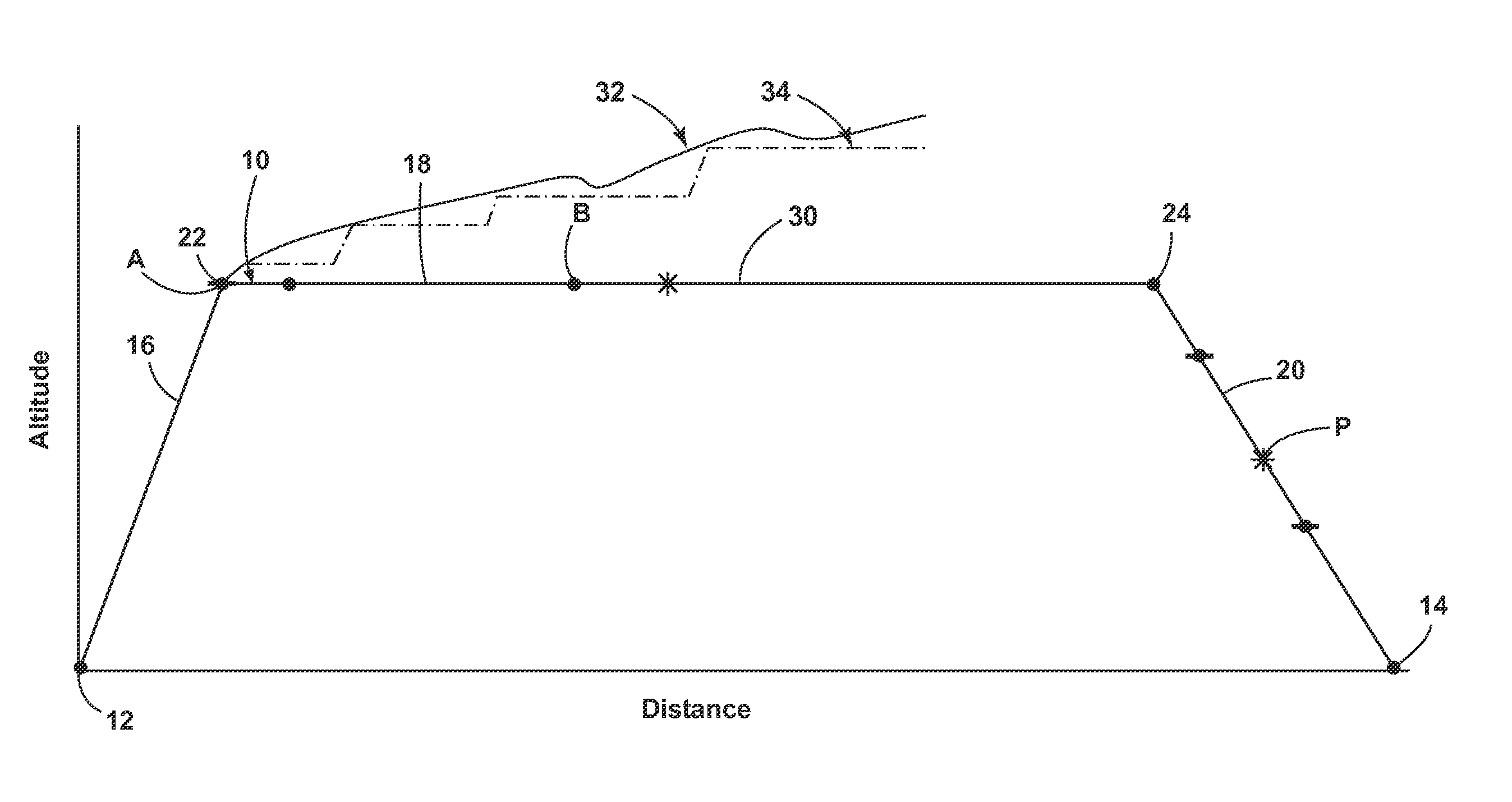
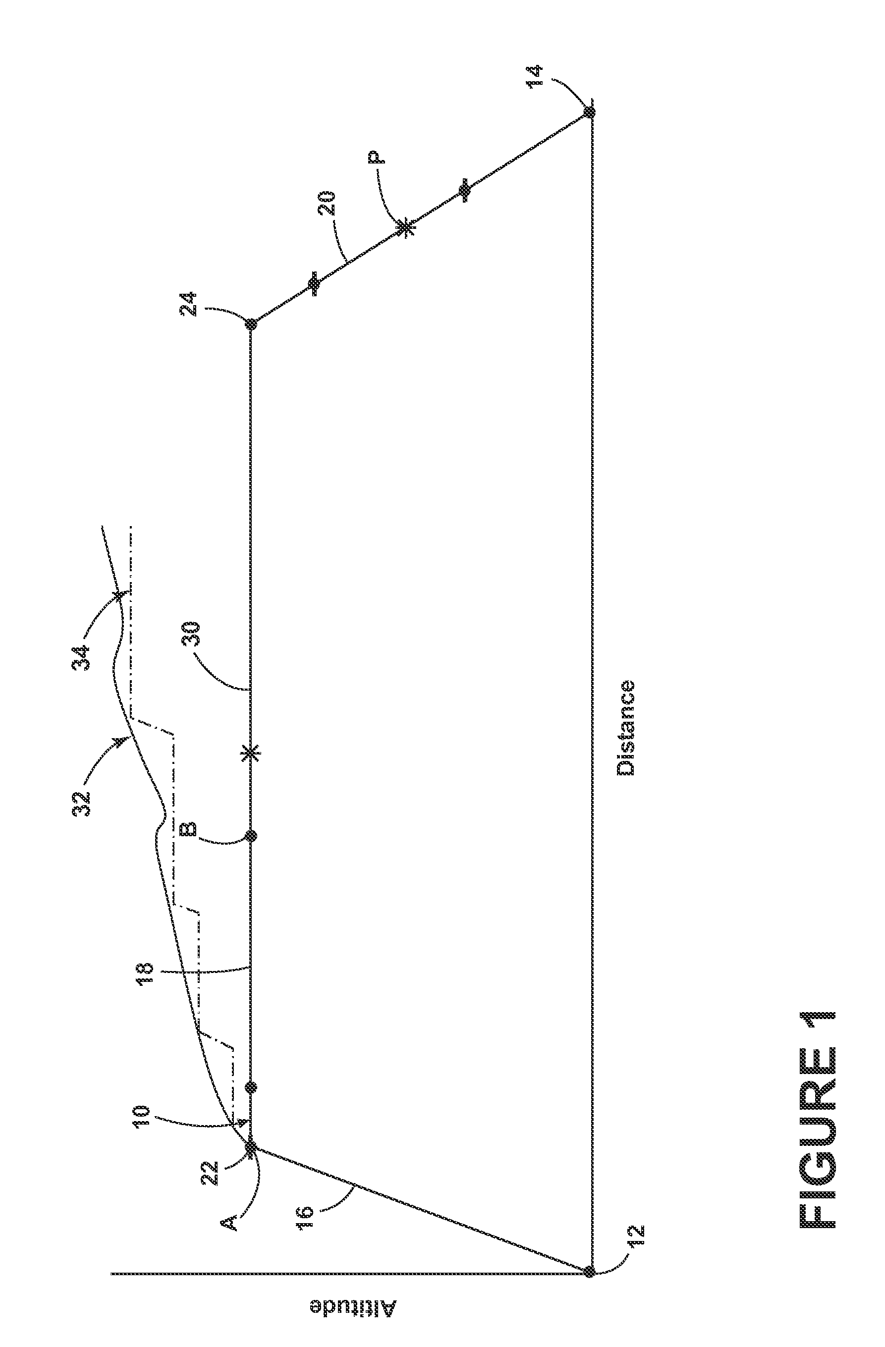
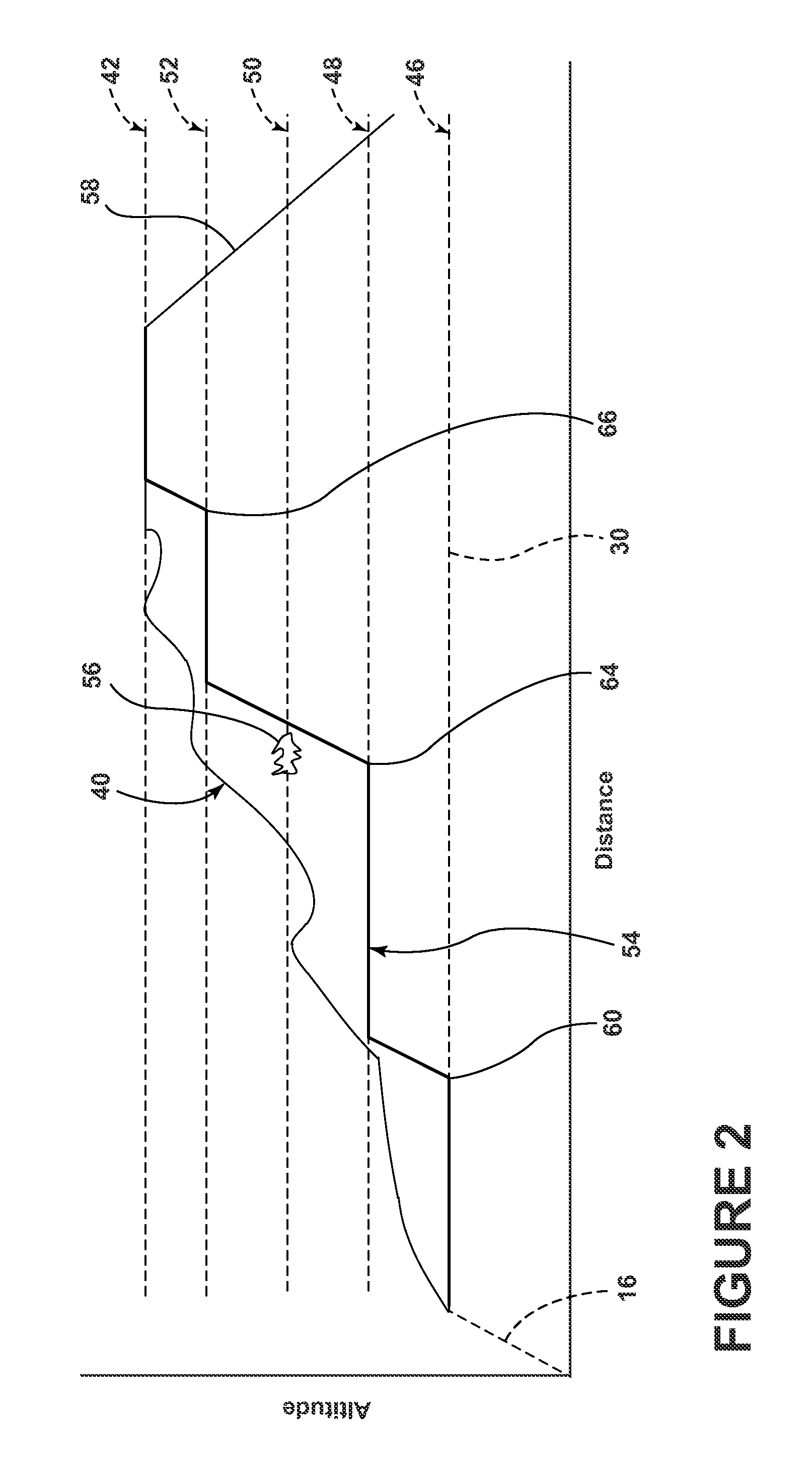
[0007]A flight path for an aircraft generally includes a climb, a cruise, and a descent. Most contemporary aircraft include a FMS for generating a flight path trajectory 10 and flying the aircraft along the flight path trajectory 10. The FMS may automatically generate the flight path trajectory 10 for the aircraft based on commands, waypoint data, and additional information such as weather data all of which may be received from an airline operations center or from the pilot. Such information may be sent to the aircraft using a communication link. The communication link may be any variety of communication mechanisms including but not limited to packet radio and satellite uplink. By way of non-limiting example, the Aircraft Communications Addressing and Reporting System (ACARS) is a digital datalink system for transmission messages between aircraft and ground stations via radio or satellite. The information may also be input by the pilot.

[0008]FIG. 1 is a schematic illustration of a f...


PUM


Abstract

A method of flying an aircraft, where the aircraft has an associated performance envelope, along a flight path based determining an altitude profile for a cruise-climb along the flight path based on the performance envelope of the aircraft and flying the aircraft along the flight path to approximate the altitude profile.

Description

BACKGROUND OF THE INVENTION[0001]In the flying of contemporary aircraft, meteorological data at waypoints along an aircraft flight path may be considered for determining an estimated time of arrival and fuel burn during an aircraft's flight. Weather data, in general, and wind data (direction and speed at altitude) and temperature data (temperature at altitude), in particular, have a significant impact on flight costs. Specifically, the fuel consumed and the duration of the flight are significantly impacted by wind speeds, wind directions, and atmospheric temperature. A flight management system (FMS) might consider wind velocity and temperature data uploaded to the FMS from a ground station via a communications system while the aircraft is in flight or input by the pilot. While the amount of the available meteorological data is large and may include multiple points along or near the aircraft flight path, there are practical limits to the real-time use of this large amount of data. Fo...

Claims


Application Information

Patent Timeline
Patent Type & Authority Patents(United States)
IPC IPC(8): G06F17/00G05D1/08G05D1/00B64C19/00G05D3/00
CPCG05D1/0005G05D1/0607
Inventor KLOOSTER, JOEL, KENNETH
Owner GE AVIATION SYST LLC
Learn More