Composite lift gate deformable section

a technology of lift gate and deformation section, which is applied in the direction of monocoque construction, domestic objects, vehicle bodies, etc., can solve the problems of excessive cost of repairing dents and mechanisms in lift gate collisions, large damage caused in the impact zone, etc., and achieve the effect of more rigidity

Active Publication Date: 2014-02-11
MAGNA INTERNATIONAL INC
View PDF26 Cites 14 Cited by
  • Summary
  • Abstract
  • Description
  • Claims
  • Application Information

AI Technical Summary

Benefits of technology

[0007]The present invention is a lift gate which has a deformable section located between an inner panel and an outer panel. The deformable section is able to deform during a low speed impact event against the outer panel, thereby preventing the inner panel from receiving any of the impact. This allows the inner panel to be significantly more rigid than the outer panel and the deformable section, and, therefore, provides the necessary structural support for the lift gate while withstanding collisions on the Impact Zone.

Problems solved by technology

But, the damage caused in this Impact Zone is also significant in part because insurance companies will vary their prices for insuring of vehicles based on how much damage occurs to a particular vehicle when subjected to an impact in this zone.
Lift gates are a rather large and relatively expensive portion of a crossover or SUV vehicle.
Additionally, the cost of repairing dents and mechanisms in a lift gate collision has gotten to be excessive.
But, with such lift gates, the lift gate outer skins and the structural support and reinforcement areas are easily damaged, which often are not easily repairable and or repaintable.
Therefore, collision damage of composite lift gates often requires replacement of the entire lift gate.

Method used


Image

  • Composite lift gate deformable section
  • Composite lift gate deformable section
  • Composite lift gate deformable section

Examples


Embodiment Construction

[0015]The following description of the preferred embodiments is merely exemplary in nature and is in no way intended to limit the invention, its application, or uses.

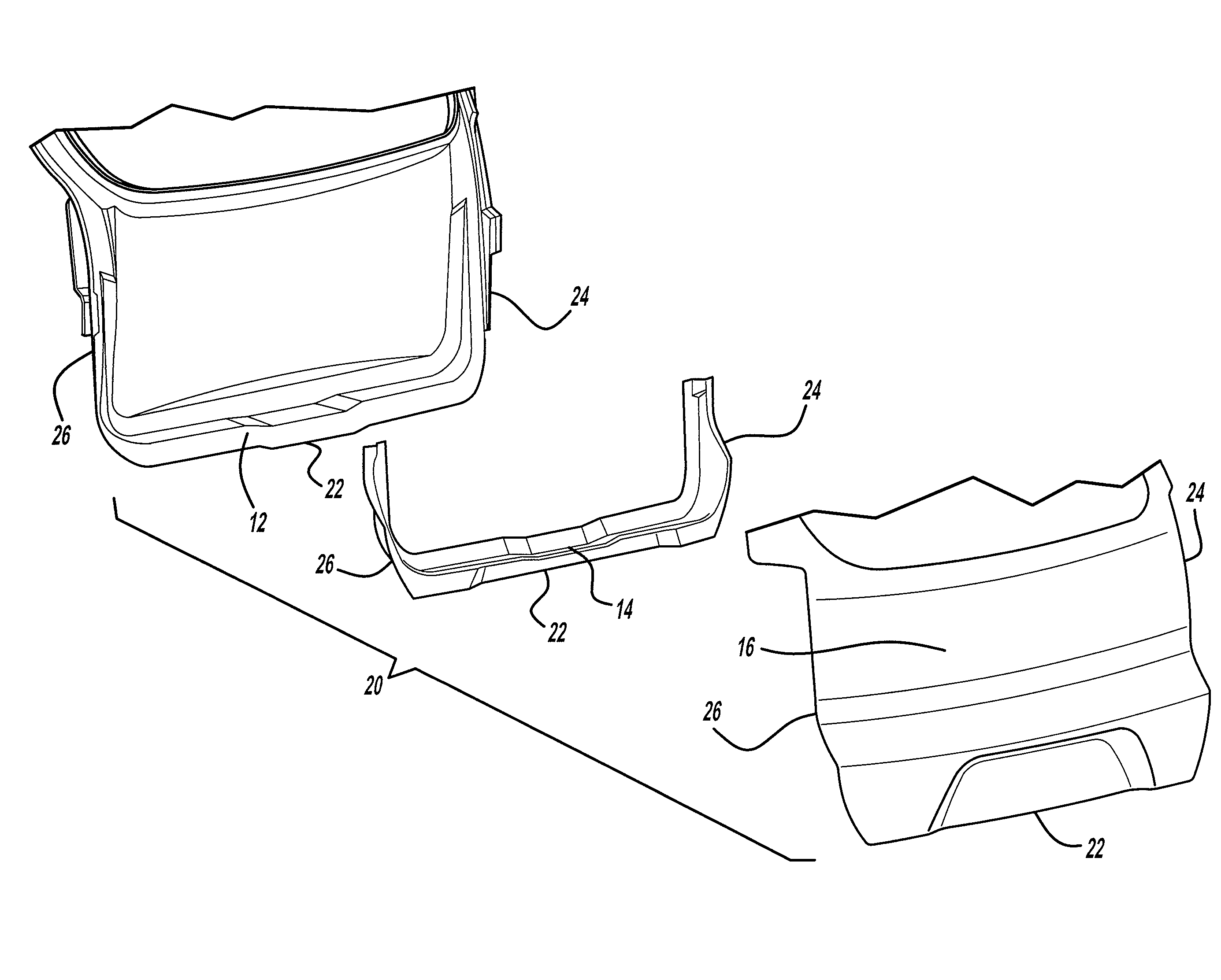
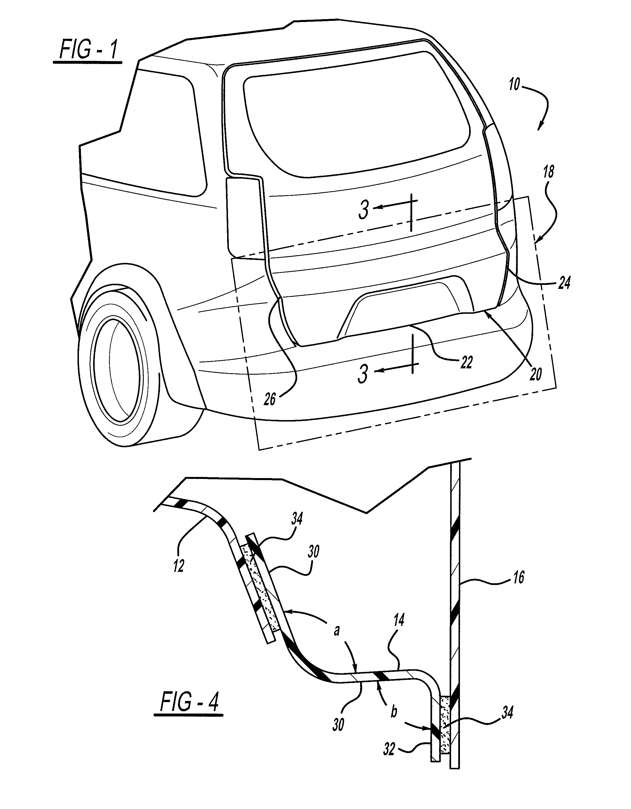
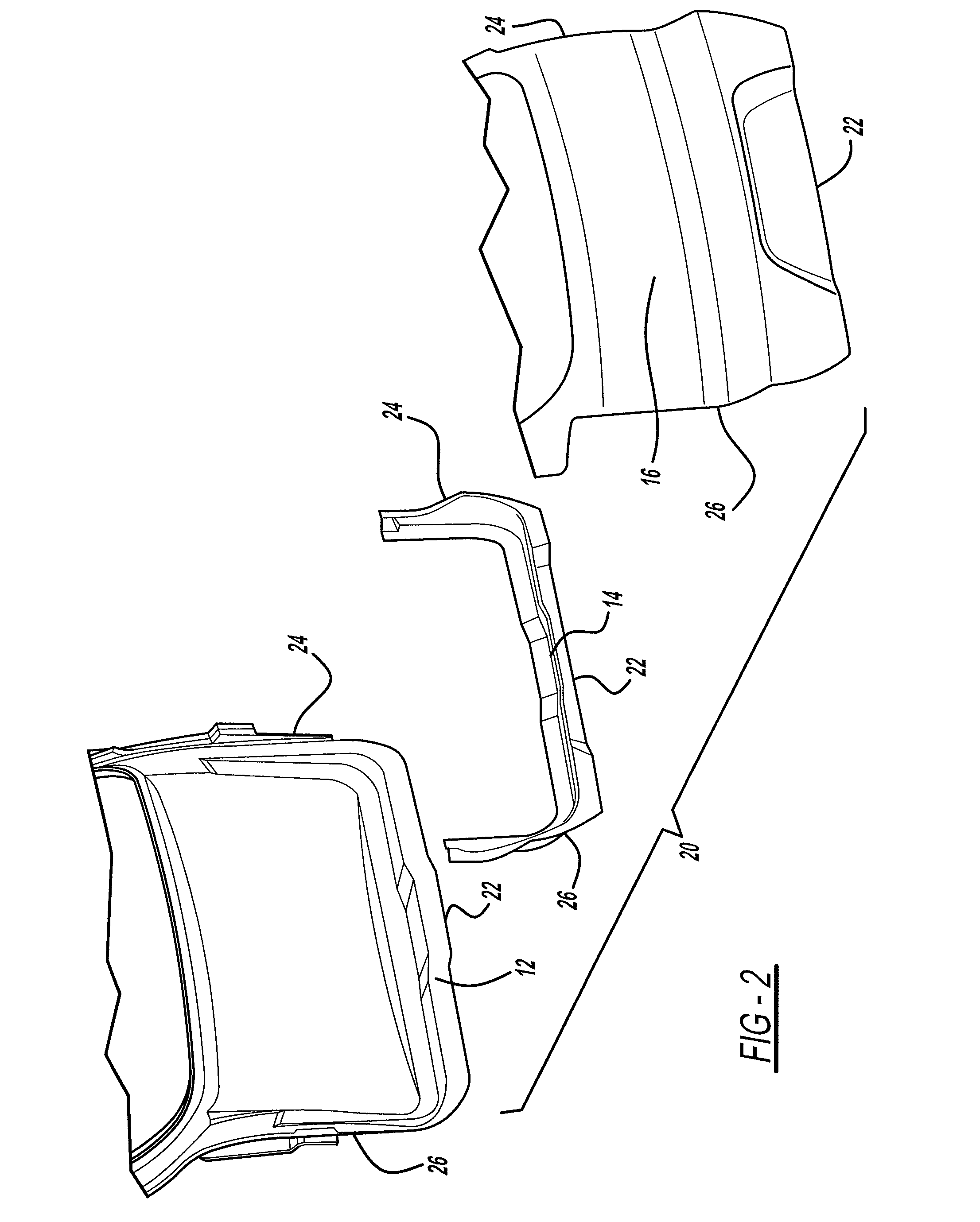
[0016]An embodiment of a composite lift gate, according to the present invention, is shown in the Figures, generally at 10. In this embodiment, the lift gate 10 includes an inner polymeric structural support panel 12, a deformable polymeric section 14, and a polymeric show surface outer panel 16.

[0017]The inner panel 12 is structural, and is substantially rigid, and provides support for the other components of the lift gate 10. The deformable section 14 is attached to the inner panel 12, as shown in FIG. 5, and the outer panel 16 is also attached to the inner panel 12 such that the deformable portion 14 is disposed between and connects at least a portion of the inner panel 12 with the outer panel 16.

[0018]The outer panel 16 is made of a flexible and resilient material suitable for defining a show surface of the lift gat...


PUM

PropertyMeasurementUnit
angleaaaaaaaaaa
speedaaaaaaaaaa
crash resistanceaaaaaaaaaa

Abstract

A lift gate having a deformable section which allows the lift gate to deform rather than break during a low speed impact event. The lift gate has a deformable section located between an inner panel and an outer panel. The deformable section is able to deform during a low speed impact event against the outer panel, thereby preventing the inner panel from receiving any of the impact. This allows the inner panel to be significantly more rigid than the outer panel and the deformable section, and, therefore, provides the necessary structural support for the lift gate while withstanding collisions on the Impact Zone.

Description

FIELD OF THE INVENTION[0001]The present invention relates to a lift gate having a deformable section which allows the lift gate to deform rather than break during a low speed impact event.BACKGROUND OF THE INVENTION[0002]Many different designs have been employed to reduce the effect of a low speed impact on a vehicle.[0003]The rear ends of vehicles are designed to meet certain impact standards. Automotive manufacturers and regulators have designed a standard referred to as an “Impact Zone” for determining the crashworthiness and crash resistance of a vehicle in a low speed impact. This zone is changed from time to time as vehicles change and regulations and the test criteria change but, typically, there is a rectangular zone with a predetermined width and height which a vehicle will be tested if it is impacted into “block” of material having those dimensions at a certain speed and the damage caused by the impact. This zone is important for crashworthiness assessment. But, the damage...

Claims


Application Information

Patent Timeline
Patent Type & Authority Patents(United States)
IPC IPC(8): B60J5/10B62D33/027
CPCB60J5/101B29C65/08B29C65/48B29C65/562B29C65/601B29C65/606B29C66/112B29C66/1122B29C66/131B29C66/543B29C66/71B29C66/7212B29C66/7392B29C66/73921B29L2031/30B29K2023/00B29K2307/04B29K2069/00B29K2067/006B29K2023/12B29K2309/08B29K2023/06B29K2023/14B29K2021/00
Inventor CRANE, MICHAEL W.SCHALTE, GARI M.COBB, THOMAS E.GUSCHEWSKI, NORMAN E.
Owner MAGNA INTERNATIONAL INC
Why Eureka
Try Eureka