
Fuel cell module

a fuel cell module and module technology, applied in the field of fuel cell modules, can solve the problems of prolonging service life and correspondingly reducing the achieve the effects of reducing the thermal stress of the fuel cell module, wide range, and high flexural elasticity

Active Publication Date: 2014-02-11
EBERSPAECHER CLIMATE CONTROL SYST GMBH & CO KG
View PDF3 Cites 0 Cited by
  • Summary
  • Abstract
  • Description
  • Claims
  • Application Information

AI Technical Summary

Benefits of technology

[0005]The present invention pertains an improved embodiment for a fuel cell module, which embodiment is characterized especially by longer service life.
[0007]The present invention is based on the general idea of connecting at least two components of the fuel cell module to one another via a compensator in a flow-carrying manner. This means that the respective compensator forms a flow-carrying or educt-carrying connection between the two components. Such a compensator is characterized in that in its longitudinal direction it has an extremely high flexural elasticity, which can reversibly compensate expansions and bending deformations in a comparatively broad range. In other words, the respective compensator permits relative motions between the components that are in connection via the compensator without unacceptably great stresses developing in the connection sites. The thermal stress of the fuel cell module is correspondingly reduced considerably, which leads to a prolongation of service life.
[0008]It is especially advantageous, on the one hand, to provide such a compensator between the residual gas burner and the heat exchanger and, on the other hand, to provide another compensator between the heat exchanger and the fuel cell or between a deflecting housing of the heat exchanger and a distributor housing of the fuel cell, on the other hand. In particular, it is possible by the use of two such compensators to allow complex, three-dimensional relative motions between the individual components of the fuel cell module. For example, the thermal expansion between the residual gas burner and the heat exchanger is markedly greater or it occurs earlier or later in time than that between the fuel cell and the heat exchanger. As a consequence, a tilting motion of the heat exchanger relative to the fuel cell occurs in case of compensators aligned in parallel. Such a tilting motion can be readily compensated by the compensators without the individual connection sites being unduly stressed in the process.

Problems solved by technology

The thermal stress of the fuel cell module is correspondingly reduced considerably, which leads to a prolongation of service life.

Method used


Image

  • Fuel cell module
  • Fuel cell module
  • Fuel cell module

Examples


Embodiment Construction

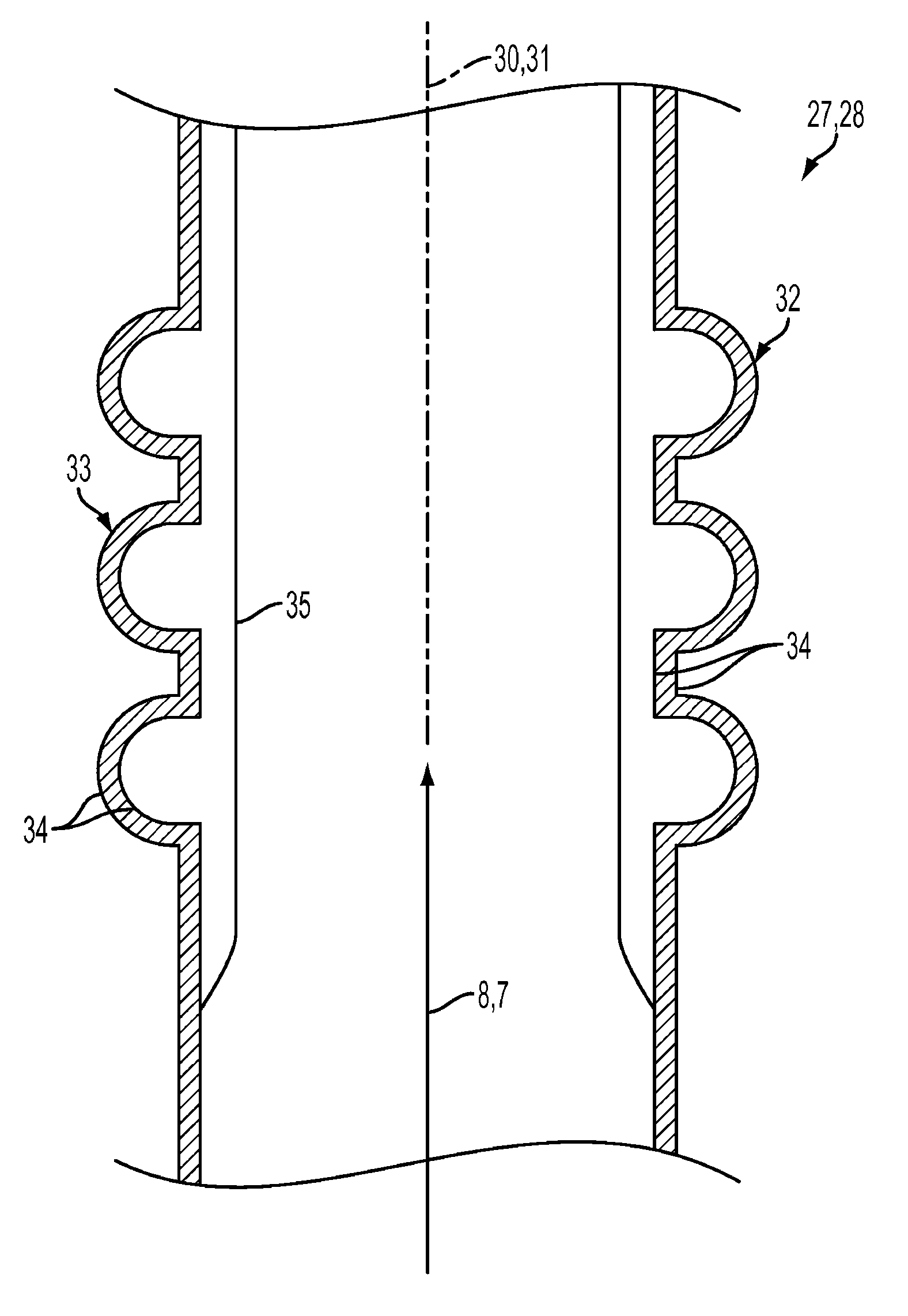
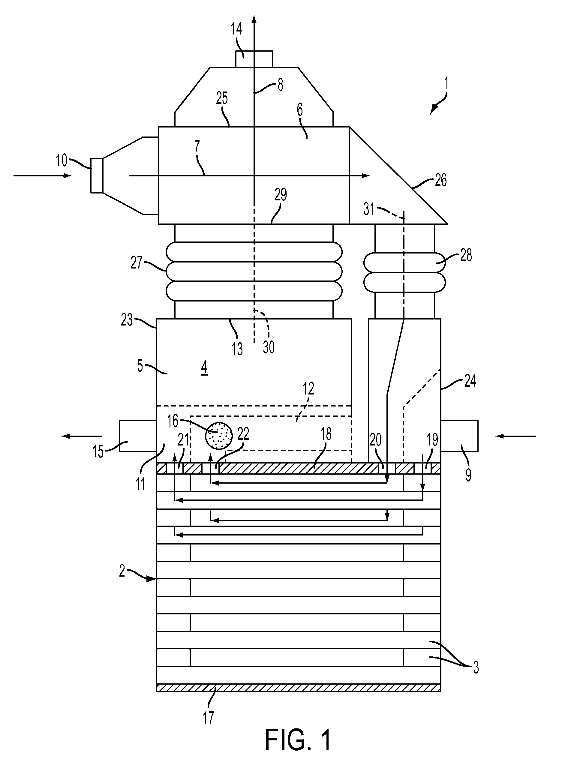
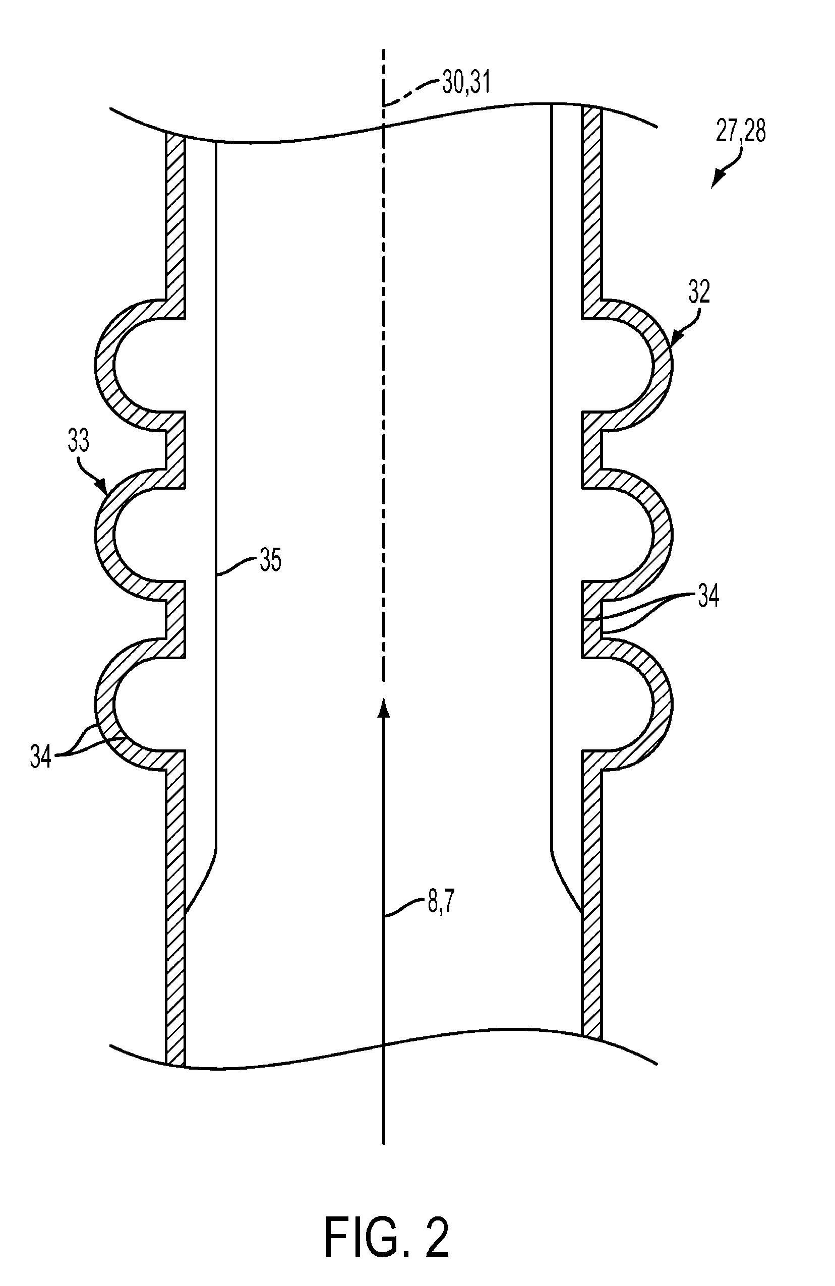
[0015]Referring to the drawings in particular, corresponding to FIG. 1, a fuel cell module 1 comprises a fuel cell 2, which is preferably a Solid Oxide Fuel Cell (SOFC). The fuel cell 2 may be composed, e.g., of a plurality of fuel cell elements 3 stacked up on one another. Module 1 has, in addition, a residual gas burner 4, which contains a combustion chamber 5. Furthermore, a heat exchanger 6 is provided, which is integrated in a cathode gas path or air path 7, on the one hand, and in a burner waste gas path 8, on the other hand, in order to couple these paths 7, 8 in a heat-transmitting manner. Paths 7, 8 are coupled with one another in cross current in the example.

[0016]Module 1 has an anode gas inlet 9, via which anode gas or combustion gas or synthesis gas can be fed. The anode gas originates, for example, from a reformer, which generates a hydrogen-containing combustion gas, namely, the anode gas, e.g., from hydrocarbon-containing fuel and air, e.g., by means of catalytic ref...


PUM

PropertyMeasurementUnit
coefficients of thermal expansionaaaaaaaaaa
coefficient of thermal expansionaaaaaaaaaa
electric currentaaaaaaaaaa

Abstract

A fuel cell module (1) with a fuel cell (2), a residual gas burner (4) and a heat exchanger (6). The service life of the module (1) can be improved by at least one compensator (27) for establishing a flow-carrying connection between the residual gas burner (4) and the heat exchanger (6).

Description

CROSS REFERENCE TO RELATED APPLICATIONS[0001]This application claims the benefit of priority under 35 U.S.C. §119 of German Patent Application DE 10 2009 017 597.0 filed Apr. 16, 2009, the entire contents of which are incorporated herein by reference.FIELD OF THE INVENTION[0002]The present invention pertains to a fuel cell module.BACKGROUND OF THE INVENTION[0003]Such a fuel cell module may have a fuel cell, a residual gas burner and a heat exchanger. The fuel cell is used in the conventional manner to generate electric current from an anode gas containing hydrogen and from a cathode gas containing oxygen. Hydrogen-containing anode waste gas of the fuel cell and oxygen-containing cathode waste gas of the fuel cell can be burned or reacted in the residual gas burner to reduce pollutant emissions and to convert chemically bound energy into heat. For example, heat can be extracted from the burner waste gas formed by the combustion reaction in the residual gas burner with the heat exchan...

Claims


Application Information

Patent Timeline
Patent Type & Authority Patents(United States)
IPC IPC(8): H01M8/24
CPCH01M8/0612Y02E60/525F28F2265/26H01M8/0662H01M2008/1293H01M8/04022Y02E60/50H01M8/04074H01M8/04097
Inventor KAUPERT, ANDREASMUNZNER, MARKUSLUZ, KLAUSBRENNER, MARTIN
Owner EBERSPAECHER CLIMATE CONTROL SYST GMBH & CO KG
Learn More