Reactor

a technology of catalyst injection pipe and polymerization reaction, which is applied in the direction of chemical/physical/physical-chemical stationary reactors, chemical apparatus and processes, chemical/physical/physical-chemical processes, etc., can solve problems such as overriding any concerns, and achieve the effect of reducing the protrusion of catalyst injection pipe and increasing the protrusion of catalyst pip

Active Publication Date: 2014-02-11
INEOS SALES (UK) LTD
View PDF18 Cites 0 Cited by
  • Summary
  • Abstract
  • Description
  • Claims
  • Application Information

AI Technical Summary

Benefits of technology

[0009]It has now been found that as the sizes of reaction zones have increased the propensity for fouling of the injection nozzles generally, by which is meant not just at the tip, increases. The present invention therefore provides an apparatus and a process which minimises the extent of protrusion of the catalyst injection pipe.
[0039]Therefore dilution and a high linear velocity both help to minimise concentration of the catalyst at the exit of the catalyst inlet pipe(s).
[0042]The process of the present invention allows reactors to be operated at relatively high space-time yields without fouling or with minimal fouling of the catalyst injection nozzle. The process is preferably operated at a space-time yield (STY) greater than 100 kg / h / m3 and more preferably greater than 150 kg / h / m3. The process is most preferably operated at a space-time yield (STY) in the range 200-400 kg / h / m3.
[0043]Similarly, by use of the catalyst inlet of the present invention it is also possible to operate the process with a relatively high concentration of the monomer in the slurry circulating in the reactor. For example, the average monomer concentration in the reaction zone may be greater than 4 wt %, in particular in the range 4 to 10 wt %, said concentration being determined relative to the total weight of the slurry. In particular, it has been found that in terms of reducing fouling, the monomer concentration in the reaction zone is less important than the protrusion of the injection nozzle, and by so minimising or reducing the protrusion high monomer concentrations may be operated without or with reduced fouling risk. (Although it is still preferred that the catalyst inlet is not located too close to a monomer feed inlet as discussed further below.)
[0045]The location of the catalyst inlet pipe(s) on the reaction zone is in general not especially critical. However, certain locations can also help to minimise contact of catalyst and monomer or comonomer until the catalyst is well dispersed.
[0058]It is preferred that the reaction zone in the present invention is substantially free from internal obstructions. It is noted that despite the reference to the use of nozzles for monomer and comonomer the reactor of U.S. Pat. No. 7,014,821 is said to be substantially free of internal obstructions. In the present invention the reaction zone is not only preferably substantially free from internal obstructions but further has no nozzles which protrude into the reaction zone, and hence provides a yet clearer flow path for the slurry in the reaction zone.

Problems solved by technology

However, to date the requirements for introducing and dispersing the catalyst have generally over-ridden any concerns about the protrusion of the injection nozzle into the reactor.

Method used


Image

  • Reactor
  • Reactor
  • Reactor

Examples


Embodiment Construction

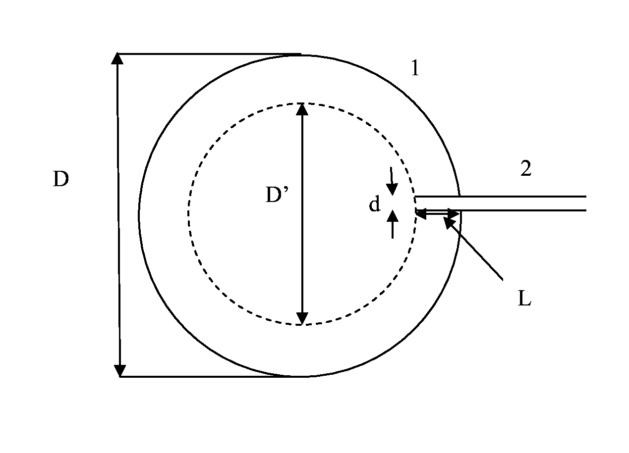
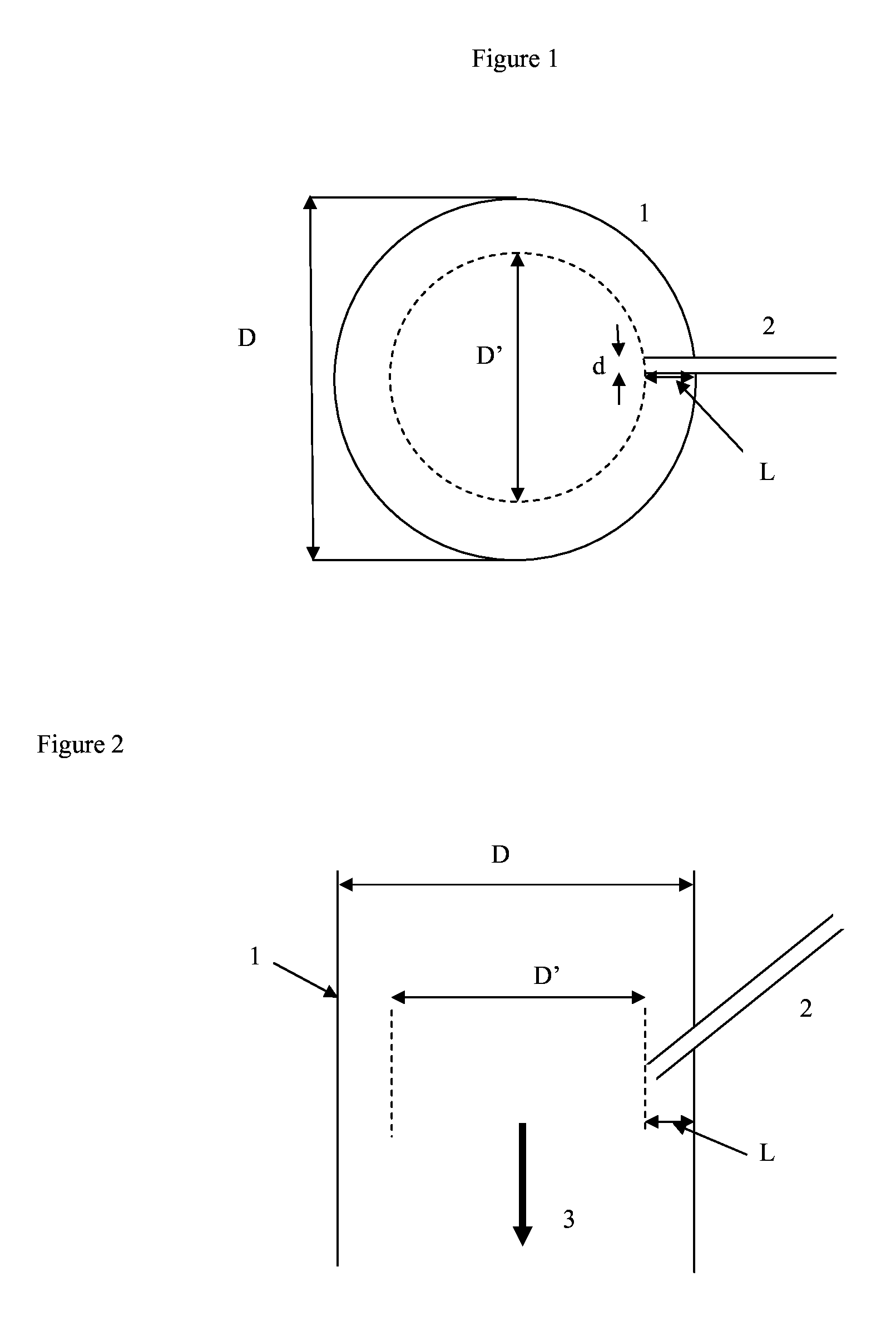
[0063]FIG. 1 shows in top view the cross-section of a loop reaction zone, 1, of diameter D. Also shown is a catalyst inlet, 2, which protrudes into the reaction zone in the form of an inlet pipe and protrudes beyond the wall of the reaction zone and into the reaction zone by a length L and having an internal diameter, d, at its exit. In the present invention L is less than 1 / 10th of the diameter of the reaction zone, D, at the point where the inlet pipe joins the reaction zone. The determination of L is also shown by reference to the diameter, D′, of the largest cylinder which is concentric with the cross-section of the reaction zone where the catalyst inlet enters the reaction zone, but which doesn't intersect any point of the inlet pipe, L being half the difference between D and D′.

[0064]FIG. 2 shows FIG. 1 as a side view. It can be seen that in this Figure the catalyst inlet, 2, protrudes into the reaction zone at an angle to the wall of the loop reaction zone of less than 90° re...


PUM

PropertyMeasurementUnit
internal diameteraaaaaaaaaa
volumeaaaaaaaaaa
linear velocityaaaaaaaaaa

Abstract

Polymerization process in a slurry loop reactor having a slurry loop reaction zone with a volume of at least 50 m3 and an internal diameter (D) of 50 cm or greater, a feed inlet for monomers and diluent, a catalyst inlet for polymerisation catalyst, and a discharge conduit for removal of polymer. Monomer, diluent and catalyst are passed into the reaction zone through their respective inlets where they form a slurry of polymer solids having a polymer solids concentration in the reaction zone of greater than 20 wt %. The space-time yield (STY) is greater than 100 kg / h / m3, and the catalyst inlet is an inlet pipe such that no part of the inlet pipe protrudes beyond the wall of the reaction zone and into the reaction zone by more than 1 / 10th of the diameter of the reaction zone at the point where the inlet pipe joins the reaction zone.

Description

[0001]This application is the U.S. national phase of International Application No. PCT / EP2011 / 055685 filed Apr. 12, 2011 which designated the U.S. and claims priority to European Patent Application No. 10162709.9 filed May 12, 2010, the entire contents of each of which are hereby incorporated by reference.[0002]The present invention relates to a reactor, and in particular to a slurry loop polymerisation reactor.BACKGROUND OF THE INVENTION[0003]In a typical slurry polymerization reaction, monomer, diluent and a particulate catalyst are fed to a reaction zone where the monomer is polymerized. The diluent does not react but the quantity of diluent supplied to the reaction zone is typically utilized to control solids concentration in the reaction zone and also to provide a convenient mechanism for introducing the catalyst into the reactor.[0004]Slurry loop reaction zones are in the form of continuous loop in which polymerisation occurs in the circulating slurry. Inlets are provided for ...

Claims


Application Information

Patent Timeline
Patent Type & Authority Patents(United States)
IPC IPC(8): C08F4/00C08F210/00B01J19/18C08F2/00
CPCC08F210/06B01J2219/00186B01J4/02B01J2219/00247C08F10/00C08F210/16B01J2219/00254B01J19/1837B01J4/002B01J19/002C08F2/06C08F2/01C08F210/08
Inventor MARISSAL, DANIELLEE, STEPHEN KEVIN
Owner INEOS SALES (UK) LTD
Why Eureka
Try Eureka