Electrical and elastomeric disruption of high-velocity projectiles

a technology of elastomeric and high-velocity projectiles, applied in the direction of reactive armour, other domestic articles, protective garments, etc., can solve the problems of large solid-metallic/all-metallic armor, heavy steel-type armor, and inability to meet the requirements of many applications, so as to achieve greater protection for vehicular occupants.

Inactive Publication Date: 2011-05-24
THE UNITED STATES OF AMERICA AS REPRESENTED BY THE SECRETARY OF THE NAVY
View PDF15 Cites 22 Cited by
  • Summary
  • Abstract
  • Description
  • Claims
  • Application Information

AI Technical Summary

Benefits of technology

[0006]In view of the foregoing, an object of the present invention is to provide a reasonably economical armor system suitable for mobility-purposed vehicles that affords greater protection of vehicular occupants from high-velocity projectiles.
[0008]According to typical inventive practice, the present invention succeeds in defeating high-velocity projectiles; in doing so, the present invention uniquely features the use of highly rate-sensitive (strain-rate-sensitivity-hardening) elastomeric material in combination with the effectuation of electrical discharge (e.g., capacitive discharge or battery discharge at comparatively low energy levels) by rigid electrically conductive plates. The present invention, as typically embodied, is characterized by a synergy of the strain-rate-sensitivity-hardening elastomer and the rigid electrically conductive plates that sandwich it. The two main projectile-disruptive components of the inventive armor system are a mechanical component and an electrical component. The plates facilitate the strain-rate-sensitivity hardening of the elastomer, the elastomer facilitates the electrical conduction by the plates, and the plates and the elastomer together exert degradative forces that defeat an intruding projectile.
[0009]A strain-rate-sensitivity-hardening elastomer has a propensity toward transient high-rate dynamic mechanical strength elevations. As typically embodied by the present invention, this propensity is enhanced by the constraining of the strain-rate-sensitivity-hardening elastomer by the two rigid electrically conductive plates, between which the strain-rate-sensitivity-hardening elastomer is sandwiched and bonded; this confined condition (i.e., between the two plates) further elevates the strength and modulus of the strain-rate-sensitivity-hardening elastomer. During a dynamic event, the present invention's strain-rate-sensitivity-hardening elastomer acts upon a transiting projectile in physical ways (e.g., change of speed, change of direction, deformation) that result in a longer duration of the projectile's transit across the strain-rate-sensitivity-hardening elastomer, thereby affording a longer duration of the present invention's electrical connectivity. During the time of the present invention's electrical connection, the strain-rate-sensitivity-hardening elastomer and the electrification act independently and in concert upon the transiting projectile so as to bring about further degradation of the projectile. In addition, the elevated mechanical strength of the strain-rate-sensitivity-hardening elastomer enables it to more effectively share loads with the two sandwiching rigid electrically conductive plates, thereby even further improving resistance of the back plate to perforation.
[0010]As typically embodied, an inventive armor system includes at least two electrically conductive (e.g., metal) plates, at least one layer of highly rate-sensitive elastomer, and an electrical power source. According to typical inventive practice, the highly rate-sensitive elastomer is electrically nonconductive (insulative). Strong electrically conductive materials that may be suitable for practicing the inventive plates include, but are not limited to, steel, titanium, titanium alloy, aluminum, aluminum alloy, and other metals and alloys. Each electrically conductive plate is connected to the electrical power source (e.g., a battery, or a bank of supercapacitors), which supplies electrical current. The electrical power source is capable of delivering a large amount of electrical power (e.g., electrical current) in a very short period of time. The electrically conductive plates are separated by the highly rate-sensitive polymer, each adjacent pair of electrically conductive plates having a highly rate-sensitive polymer layer situated therebetween. Each contiguous plate-polymer-plate trio describes a sandwich construction of two electrically conductive outside plates and a highly rate-sensitive polymer core.
[0013]The highly rate-sensitive elastomer thus serves to increase the time period of the penetrative projectile's traversal of the “gap” (which the highly rate-sensitive elastomer fills) between the two adjacent electrically conductive plates. The increase in traversal duration is beneficial because the time is extended during which the electrical circuitry can be switched to the closed position and the circuitry can be maintained in a closed state, thereby extending the time during which the accompanying electrical energy can act upon the penetrative projectile. Moreover, the increase in amount of electro-influential time permits lower levels of electrical current to be conducted in order to defeat the penetrative projectile. The present invention thus advantageously permits use of low-power electrical units that tend to be light, low-cost (e.g., implementing commercial off-the-shelf components), and portable. For instance, supercapacitors (also known as “ultracapacitors”) are commercially available from companies such as Maxwell Technologies Inc., 9244 Balboa Avenue, San Diego, Calif.
[0017]A strain-rate-sensitivity-hardening elastomer has the quality of reacting instantaneously to impact (for instance, at strain rates in the 103 / sec-106 / sec range) so as to temporarily become significantly more rigid than it is in its normal (non-impacted) state, and of then returning to its normal elastic (e.g., viscoelastic) state shortly after absorbing energy associated with the impact. Otherwise expressed, a strain-rate-sensitivity-hardening elastomer is in an elastic state before absorbing energy from a projectile, then tends toward a rigid state (i.e., “hardens” or “stiffens”) when absorbing energy from the projectile, and then tends toward an elastic state after absorbing energy from the projectile. A strain-rate-sensitivity-hardening elastomer exhibits greatly increased transient mechanical property changes under rapid loading, such as when exposed to explosively generated forces, and exhibits high elongations during and after load removal.

Problems solved by technology

Thick and heavy metallic armor, such as made of steel, is capable of defeating high-velocity projectiles, but is not feasible for many applications.
The drawbacks of massive solid-metallic / all-metallic armor—e.g., increase in vehicular weight, decrease in vehicular range, decrease in vehicular speed, decrease in mean time between vehicular repairs, and decrease in vehicular lifetime—are especially manifest for applications involving smaller, lighter vehicles such as trucks, high mobility multipurpose wheeled vehicles (HMMWVs, popularly referred to as HUMVEE®s), and other mobile land vehicles.
Armor systems have been considered that utilize non-metallic (e.g., polymeric or ceramic) materials that are lighter than metallic armor materials, but these armor systems can be expensive and are not entirely satisfactory in defending against high-velocity projectiles such as explosively formed projectiles (EFPs), which are designed to hurl fragments at high velocities upon detonation of an explosive.

Method used


Image

  • Electrical and elastomeric disruption of high-velocity projectiles
  • Electrical and elastomeric disruption of high-velocity projectiles
  • Electrical and elastomeric disruption of high-velocity projectiles

Examples


Embodiment Construction

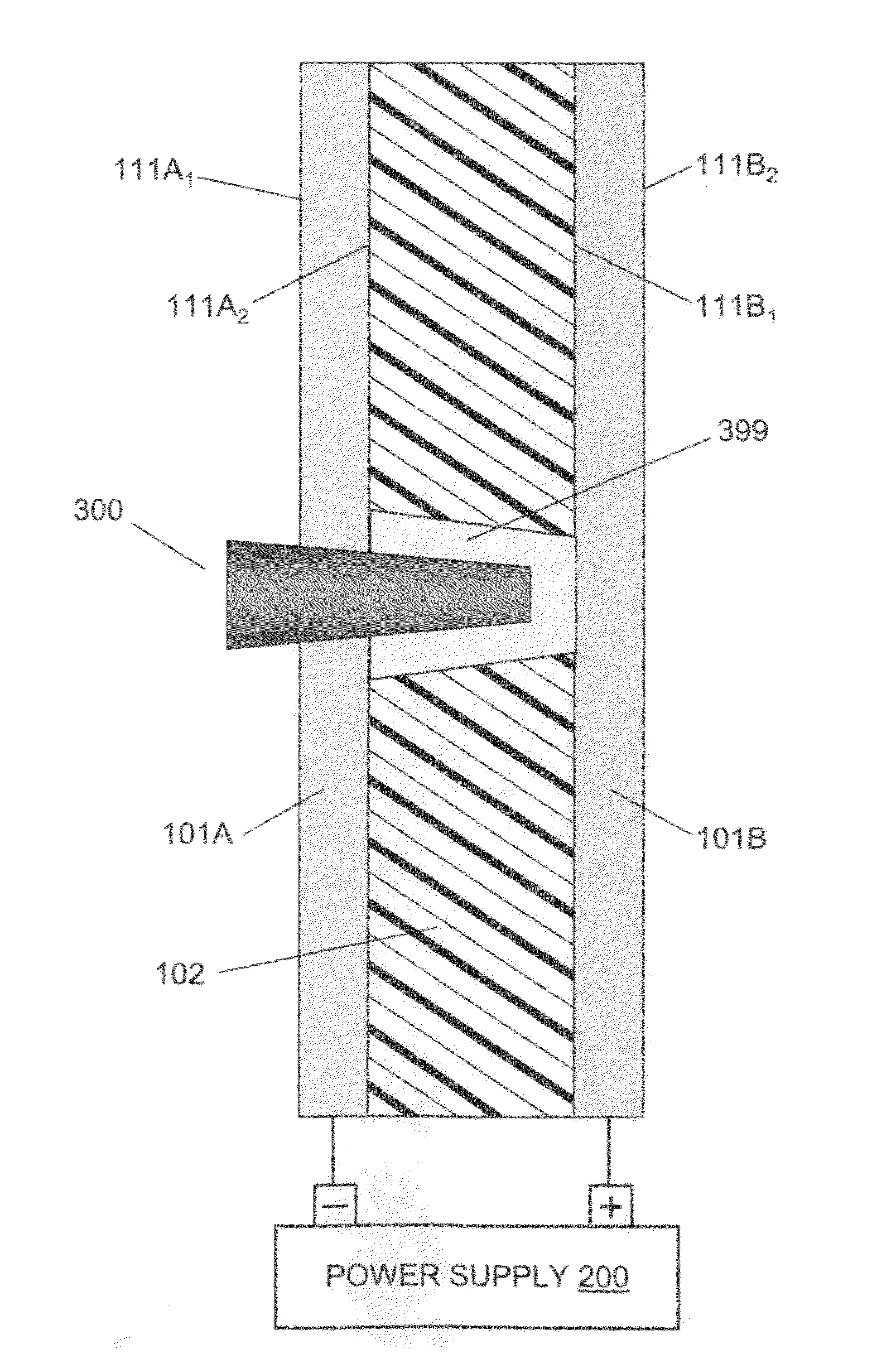
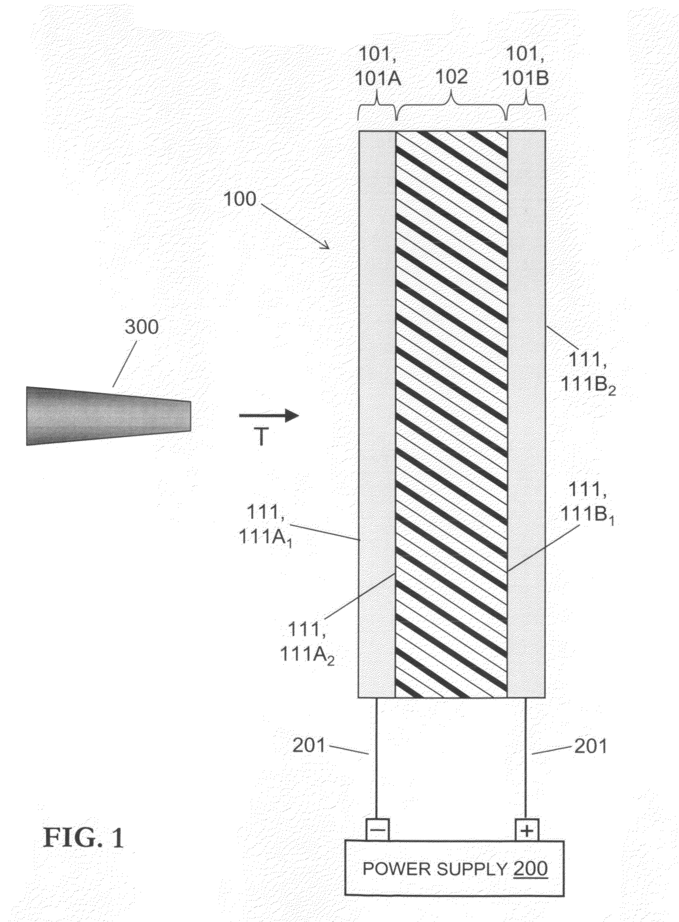
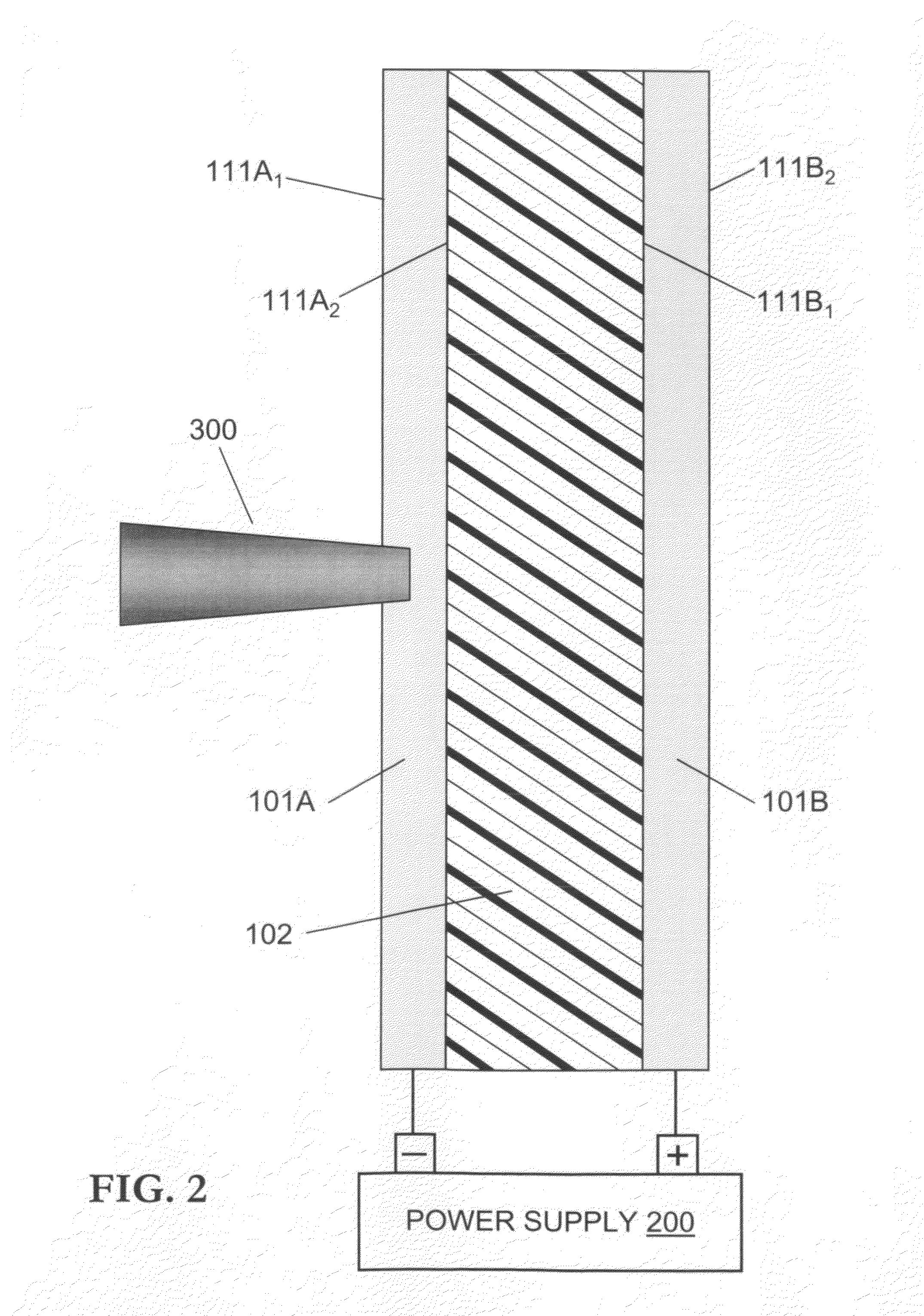
[0029]Referring now to FIG. 1, the inventive armor system includes armor structure 100, electrical power supply 200, and electrical conductors (e.g., wires) 201. Electrical power supply 200 is electrically connected, via electrical conductors 201, to the two plates 101, viz., plate 101A and plate 101B. Plates 101A and 101B respectively constitute the negative and positive electrodes of an open (but closable) circuit described by plates 101A and 101B, conductors 201, and power supply 200. Armor structure 100 represents a composite laminar material system—more specifically, a sandwich construction—that includes two outside rigid electrically conductive (e.g., metallic) plates 101 and, therebetween, a core layer of highly rate-sensitive elastomer 102.

[0030]Plates 101A and 101B are shown to be planar, parallel, and geometrically congruent. Plate 101A, the front (strike) plate relative to projectile 300, has a flat front (strike) surface 111A1 and a flat back surface 111A2. Plate 101A, t...


PUM

PropertyMeasurementUnit
Young's modulusaaaaaaaaaa
electrical connectivityaaaaaaaaaa
strain rateaaaaaaaaaa

Abstract

According to typical inventive practice, an armor structure includes n≧1 highly-rate-sensitive elastomeric layers and n+1≧2 metallic layers, alternately configured. Each metallic layer is electrically connected to a power supply that includes, e.g., battery(ies) and / or supercapacitor(s). Each adjacent pair of metallic layers sandwiches a highly-rate-sensitive elastomeric layer and forms, with the power supply, an uncompleted electrical circuit. A high-velocity projectile that penetratively encroaches upon a highly-rate-sensitive elastomeric layer is subjected to electrical current by virtue of completion of the uncompleted circuit that includes the two sandwiching metallic layers. The circuit is completed by physical (and hence, electrical) contact, bridging the two sandwiching metallic layers, of the projectile and / or its plasma sheath (which at least partially surrounds the projectile's outside surface due to friction between the projectile and the highly-rate-sensitive elastomeric layer). The highly-rate-sensitive elastomeric layer's projectile-hindering mechanical influence temporally lengthens the projectile-hindering electrical influence.

Description

CROSS-REFERENCE TO RELATED APPLICATIONS[0001]This application is a continuation-in-part of U.S. nonprovisional application Ser. No. 11 / 443,845, filed 22 May 2006 now U.S. Pat. No. 7,794,808, hereby incorporated herein by reference, entitled “Elastomeric Damage-Control Barrier,” joint inventors Philip John Dudt and Roshdy George S. Barsoum, U.S. Patent Application Publication 2007 / 0093158 A1, published 26 Apr. 2007, which is a continuation-in-part of U.S. nonprovisional application Ser. No. 10 / 864,317, filed 10 Jun. 2004, now U.S. Pat. No. 7,300,893 B2, issued 27 Nov. 2007, hereby incorporated herein by reference, entitled “Armor Including a Strain Rate Hardening Elastomer,” joint inventors Roshdy George S. Barsoum and Philip Dudt, U.S. Patent Application Publication 2007 / 0111621 A1, published 17 May 2007, which claims the benefit of U.S. provisional application No. 60 / 564,584, filed 23 Apr. 2004, hereby incorporated herein by reference, entitled “Armor Including a Strain Rate Harden...

Claims


Application Information

Patent Timeline
Patent Type & Authority Patents(United States)
IPC IPC(8): F41H5/00F41H11/00
CPCB29C70/70B32B3/10F41H5/0492F41H5/007F41H5/0428F41H5/0442B29K2995/0089B32B2307/56B32B2571/00
Inventor WINCHESTER, CLINTON S.DUDT, PHILIP J.DEJARNETTE, HAMPTON M.
Owner THE UNITED STATES OF AMERICA AS REPRESENTED BY THE SECRETARY OF THE NAVY
Why Eureka
Try Eureka